Capacitor, particularly intermediate circuit capacitor for a multiphase system

Active Publication Date: 2021-04-15
ROBERT BOSCH GMBH
View PDF0 Cites 0 Cited by
  • Summary
  • Abstract
  • Description
  • Claims
  • Application Information

AI Technical Summary

Benefits of technology

[0014]It has proven to be advantageous if the at least one connecting element is in the form of a pin and is plugged into at least one opening in the second voltage layer and/or is welded to the second voltage layer. In this way, the contact-making element can advantageously be fitted easily on the second voltage layer by virtue of the connecting element and can be fastened to said connecting element easily and in a stable manner.
[0015]If the contact-making element comprises a further side region, wherein the side region and the further side region are arranged on opposite sides of the capacitor structure, the advantage results whereby a side region is provided on the two opposite sides of the capacitor structure, which can also be used as a stable and compact receptacle for the capacitor structure. The capacitor structure can advantageously be pushed in between the two side regions of the contact-making element easily, for example during manufacture. The capacitor structure can thus be inserted in the receptacle and in this way advantageously adjusted and protected. Therefore, the capacitor is advantageously compact and provides an advantageous receptacle for a multiplicity of standard capacitor structures and therefore proves i

Problems solved by technology

Owing to the repeated occurrence of switching operations, frequency-dependent

Method used


Image

  • Capacitor, particularly intermediate circuit capacitor for a multiphase system
  • Capacitor, particularly intermediate circuit capacitor for a multiphase system
  • Capacitor, particularly intermediate circuit capacitor for a multiphase system

Examples


Example

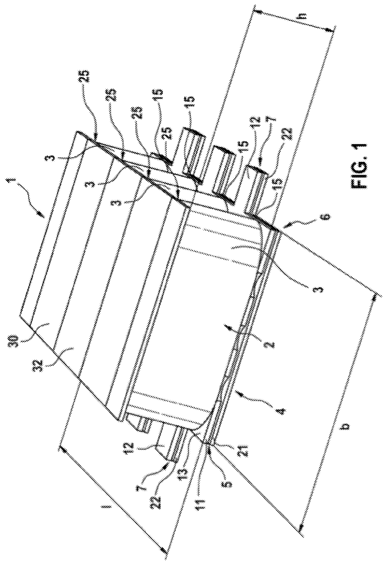
[0022]FIG. 1 shows a schematic illustration of an exemplary embodiment of the capacitor 1 according to the invention. The capacitor 1 comprises a first voltage layer 11 and a second voltage layer 21. The first voltage layer 11 and the second voltage layer 21 form a region of overlap 4, in which the first voltage layer 11 and the second voltage layer 21 are arranged parallel to one another and directly one above the other, spaced apart from one another by a gap 5, on a base side 6 of the capacitor 1. The voltage layers 11, 21 are manufactured from an electrically conductive material such as metal, for example, such as copper, for example. The voltage layers 11, 21 can be flat and can be manufactured from metal sheets, for example. The first voltage layer 11 and the second voltage layer 21, as in this exemplary embodiment, can have substantially, i.e. apart from the cutouts 14 provided in the first voltage layer 11, the same areal extent. Thus, optimized guidance of the current paths ...


PUM


Abstract

The invention relates to a capacitor (1), particularly an intermediate circuit capacitor for a multiphase system, with a first voltage layer (11) and a second voltage layer (21), the first voltage layer (11) and the second voltage layer (21) forming an overlapping region (4) in which the first voltage layer (11) and the second voltage layer (21) are parallel to each other and arranged directly one above the other, at a distance from each other by means of a gap (5), on a base side (6) of the capacitor (1), with at least one capacitor structure (3) comprising at least one dielectric (2), arranged on an upper side (13) of the first voltage layer (11), facing away from the second voltage layer (21), the first voltage layer (11) being in electroconductive contact with a first terminal (15) of the capacitor structure (3) and the second voltage layer (21) being in electroconductive contact with a second terminal (25) of the capacitor structure (3) by means of a contacting element (30). According to the invention, the first voltage layer (11) has at least one recess (14) through which the contacting element (30) is guided.

Description

BACKGROUND OF THE INVENTION[0001]The invention relates to a capacitor, particularly an intermediate circuit capacitor for a polyphase system.[0002]In power electronics, a plurality of electrical networks is coupled in terms of energy on a common DC voltage plane via electrical capacitors in an intermediate circuit of converters. Owing to the repeated occurrence of switching operations, frequency-dependent high power losses occur as a result of the alternating currents in the phases. It is known that, owing to flat current conduction and owing to the magnetic interaction between the current layers effected with an opposite direction of current flow, a marked reduction in the inductance resulting from the interconnection and therefore markedly reduced power losses result.SUMMARY OF THE INVENTION[0003]In accordance with the invention, a capacitor, particularly an intermediate circuit capacitor for a polyphase system, comprising a first voltage layer and a second voltage layer is propos...

Claims


Application Information

Patent Timeline
IPC IPC(8): H01G2/22H01G4/38H01G4/005
CPCH01G2/22H01G4/005H01G4/38H01G2/04H01G4/40H02M7/003
Inventor KESSLER, MARTIN
Owner ROBERT BOSCH GMBH
Why Eureka
Try Eureka