Stored material detecting switch

Inactive Publication Date: 2007-05-10
HOSHIZAKI ELECTRIC CO LTD
View PDF12 Cites 0 Cited by
  • Summary
  • Abstract
  • Description
  • Claims
  • Application Information

AI Technical Summary

Benefits of technology

[0007] The invention has been made to eliminate such problems. Therefore, it is an object of the present invention to provide a stored material detecting switch which is inexpensive, can be fitted easily, and enables reliable detection of a storage level regardless of a direction from which a stored material such as ice comes into contact with the stored material detecting switch.

Problems solved by technology

However, the rod member to which the magnet is fixed is a rigid body, so the ice storage detecting switch cannot operate normally unless the weight is pressed laterally, which may cause malfunction.
However, a light-emitting portion and a light-receiving portion or a light-reflecting portion need to be installed accurately, which involves time and effort for a fitting operation and a high cost.

Method used


Image

  • Stored material detecting switch
  • Stored material detecting switch
  • Stored material detecting switch

Examples


first embodiment

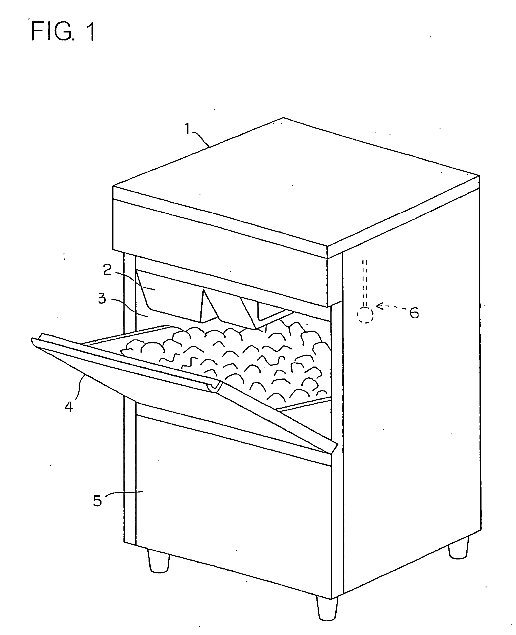
[0018]FIG. 1 shows an ice making machine fitted with an ice storage detecting switch according to a first embodiment of the present invention. An ice making portion 2 is disposed in an upper portion of an ice making machine body 1 having a shape of a rectangular parallelepiped, and an ice storage chamber 3 is formed below the ice making portion 2. An opening / closing door 4 is provided in front of the ice storage chamber 3, and blocks of ice in the ice storage chamber 3 can be taken out by opening the opening / closing door 4. A machinery chamber 5 for accommodating a compressor forming a refrigeration circuit and the like is disposed below the ice storage chamber 3.

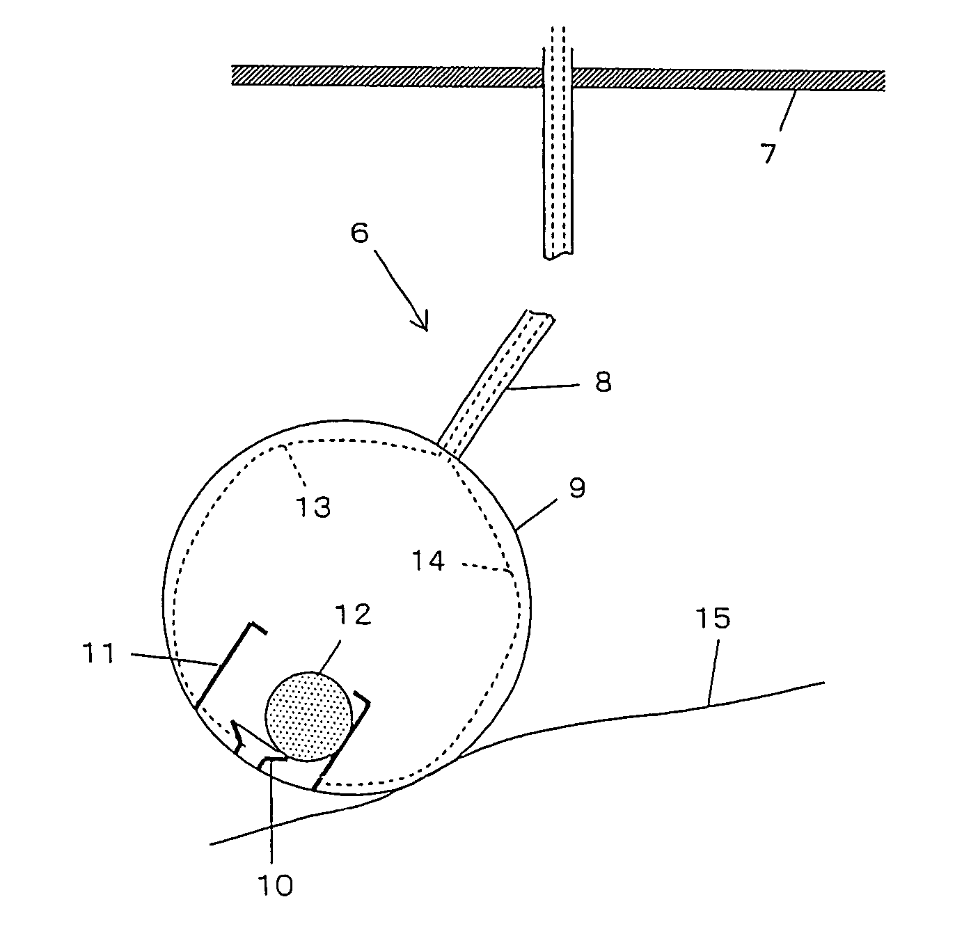
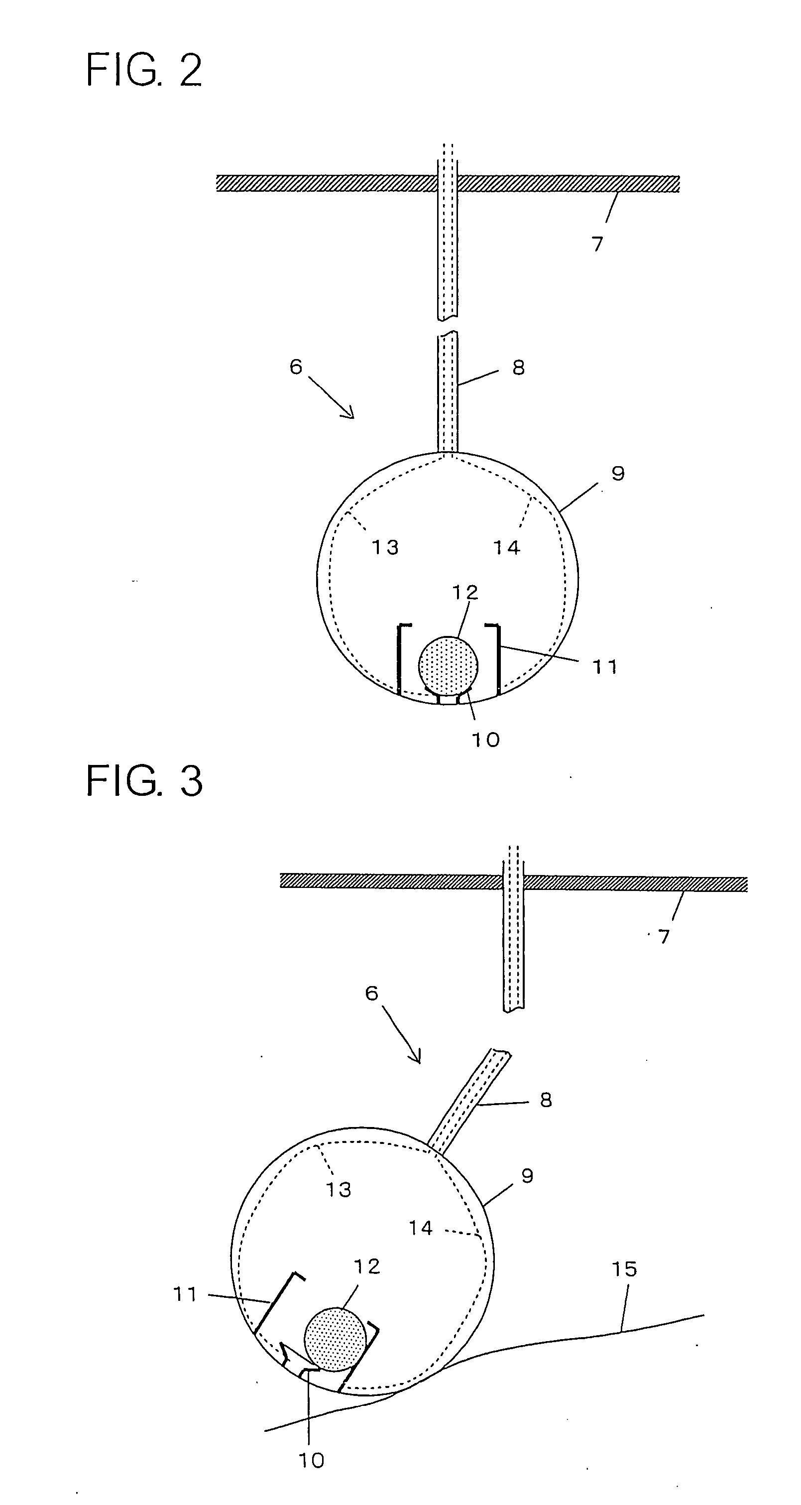
[0019] The blocks of the ice produced in the ice making portion 2 are sequentially stored in the ice storage chamber 3. A ceiling portion of the ice storage chamber 3 is fitted with an ice storage detecting switch 6. When an ice level in the ice storage chamber 3 rises to reach the ice storage detecting switch 6, a detecti...

second embodiment

[0026]FIG. 4 shows an ice storage detecting switch 16 according to the second embodiment of the present invention. This ice storage detecting switch 16 is obtained by modifying the ice storage detecting switch 6 of the first embodiment shown in FIG. 2 such that, instead of employing the ball receiver 10 and the peripheral wall 11 fixed in the resin ball 9, a proximity switch 17 is fixed to the bottom portion of the resin ball 9, an annular guide 18 is fixed to an outer peripheral portion of the proximity switch 17, and the ball 12 formed of a conductive material is laid on the proximity switch 17 in a rollable manner. The guide 18 has an inner diameter larger than the diameter of the ball 12, and the signal wires 13 and 14 are connected to the proximity switch 17.

[0027] The proximity switch 17 outputs an ON signal via the signal wires 13 and 14 when the ball 12 is located in proximity thereto, and outputs an OFF signal when the ball 12 moves away therefrom. In the second embodiment...

third embodiment

[0031]FIG. 6 shows an ice storage detecting switch 26 according to the third embodiment of the present invention. This ice storage detecting switch 26 is obtained by modifying the ice storage detecting switch 6 of the first embodiment shown in FIG. 2 such that, instead of employing the ball receiver 10, the peripheral wall 11, and the ball 12 provided in the resin ball 9, a reed switch 27 is fixed to the bottom portion of the resin ball 9 and a magnet 28 is suspended in the resin ball 9 in a rockable manner so as to be located in proximity to the reed switch 27 when the resin ball 9 is not inclined. The signal wires 13 and 14 are connected to the reed switch 27.

[0032] The reed switch 27 outputs an ON signal via the signal wires 13 and 14 when the magnet 28 is located in proximity thereto, and outputs an OFF signal when the magnet 28 moves away therefrom. In the third embodiment of the present invention, the reed switch 27 and the magnet 28 form the stored material detecting means. ...


PUM


Abstract

A stored material detecting switch includes: a hollow case; stored material detecting device accommodated in the case, for outputting a detection signal when the case is inclined at an angle equal to or more than a predetermined angle; and suspension member for suspending the case in a storage chamber, in which the detection signal outputted from the stored material detecting device at a time when the case is inclined at the angle equal to or more than the predetermined angle through contact with a stored material in the storage chamber is used to detect a storage level in the storage chamber.

Description

BACKGROUND OF THE INVENTION [0001] 1. Field of the Invention [0002] The present invention relates to a stored material detecting switch, and more particularly to a switch for detecting an ice level in an ice storage chamber. [0003] 2. Description of the Related Art [0004] In general, in an ice making machine having a structure in which blocks of ice produced in an ice making portion are stored in an ice storage chamber, an ice storage detecting switch for detecting an ice level in the ice storage chamber to control an ice making operation in accordance with an ice storage amount is disposed. For the ice storage detecting switch of this type, there are known various mechanisms and methods. For instance, a mechanical ice storage detecting switch fitted on an inner wall surface of an ice storage chamber is disclosed in Japanese Utility Model Application Laid-open No. 54-179568. A rod member having a weight formed at its lower end is suspended in a rockable manner, and a magnet is fixed...

Claims


Application Information

Patent Timeline
IPC IPC(8): F25C1/00G01F23/00G08B21/00
CPCF25C5/187G01F23/0007G01F23/44H01H35/186
Inventor TOYA, CHIYOSHINOJIRI, MOTOMI
Owner HOSHIZAKI ELECTRIC CO LTD
Why Eureka
Try Eureka