Multi-control entry door hardware

a multi-control, entry door technology, applied in the direction of receiver monitoring, transmission monitoring, instruments, etc., can solve the problems of detracting from the ornamental or decorative style of the associated entry, and the associated keypad housing occupying a relatively large area or amount of real esta

Active Publication Date: 2016-09-13
SCHLAGE LOCK
View PDF21 Cites 6 Cited by
  • Summary
  • Abstract
  • Description
  • Claims
  • Application Information

AI Technical Summary

Problems solved by technology

Yet, such keypads often have a relatively large configuration, which may result in the associated keypad housing occupying a relatively large area or amount of real estate.
Yet, the inclusion of a hinged door typically adds to the overall size and / or bulk of the keypad housing.
Further, in at least certain situations, the size of the keypad housing may result in the keypad housing detracting from the ornamental or decorative style of the associated entry door or structure.
Yet, such illumination, particularly with the relatively large size of telephone style keypads, may consume relatively large amounts of electrical power.
Additionally, the relatively large size of the keypad may translate into slower time, or more concentration, on the part of the user when locating the specific key(s) that is / are to be pressed when entering the security code via the keypad.
Further, over time, a wear pattern may develop on the particular keys that are pressed when entering the security code, which may provide an indication of the correct security code, and thereby compromise the security of the electronic coded entry lock.

Method used


Image

  • Multi-control entry door hardware
  • Multi-control entry door hardware
  • Multi-control entry door hardware

Examples


Embodiment Construction

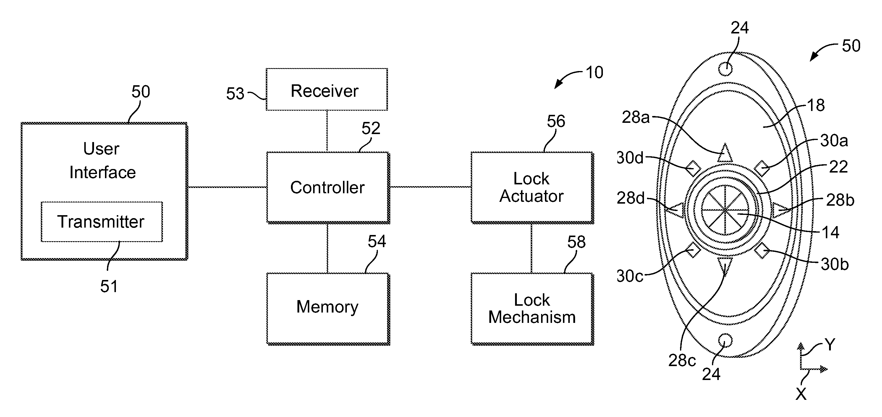
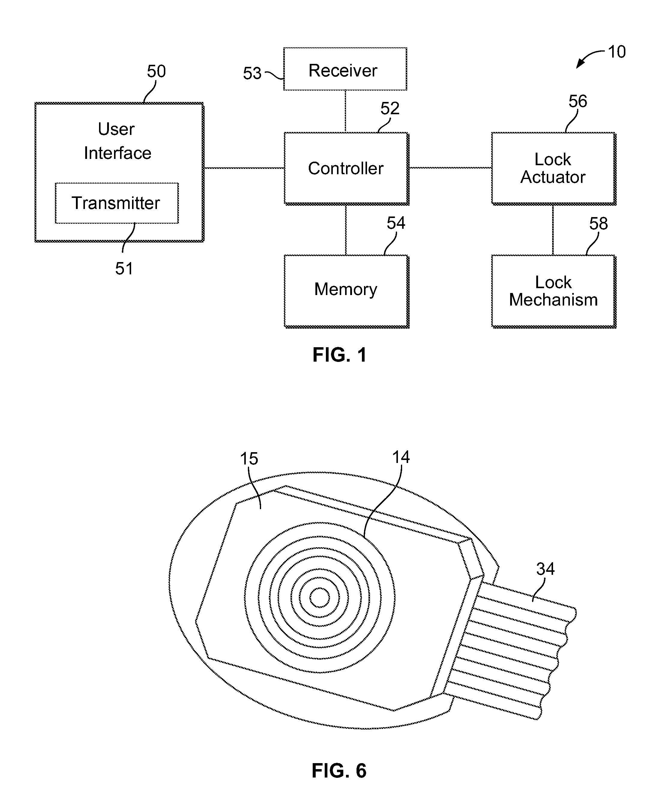
[0020]FIG. 1 illustrates a block diagram of an electronic coded entry lock 10 according to an embodiment of the present invention. The electronic coded entry lock 10 includes a user interface 50 through which a user may at least input a security code. The inputted security code may be used to control the unlocking and locking of the electronic coded entry lock 10 and / or for opening and closing the associated entry door. The user interface 50 may receive electrical power from a variety of different power sources. For example, according to certain embodiments, the user interface 50 may be battery powered. However, according to other embodiments, the user interface 50 may hardwired to a central power source, such as, for example, being wired to a circuit that also provides electrical power for a door bell.

[0021]The user interface 50 may be housed with, or be remote from, a controller 52, such as, for example, a microprocessor, that is configured to control the operation of a lock actua...


PUM


Abstract

An electronic coded entry lock that includes a multifunction switch having an actuator and a circuit member. The actuator is configured to be displaced to a plurality of input positions. For example, the actuator may be displaced to at least four, and in some instances at least eight, input positions. Further, the actuator may have at least two axes of movement. Moreover, the actuator may be configured for two or three dimensional movement. When the actuator is displaced to an input position, the circuit member may provide a signal associated with that input position. The controller may determine whether the signals provided by the circuit member correspond to a security code for the electronic coded entry lock. If the signal(s) does / do correspond to the security code, the controller may generate a command to actuate a lock actuator that displaces at least a component of a lock mechanism.

Description

RELATED APPLICATIONS[0001]This application claims the benefit of U.S. Provisional Application No. 61 / 761,824, filed Feb. 7, 2013, which is incorporated herein by reference in its entirety.BACKGROUND OF THE INVENTION[0002]Entry doors often include hardware in the form of a security mechanism to control ingress and egress through an entry. Security mechanisms may take a variety of different forms, such as, for example, electronic coded entry locks. Often, operation of electronic coded entry locks is controlled by a numerical style keypad. More specifically, through the use of the individual keys of the keypad, a user may input a security code that initiates a protocol that drives components of the electronic coded entry lock to lock or unlock the electronic coded entry lock, and / or open or close the entry door.[0003]For example, the opening and closing of a garage door may be controlled via a remote keypad that is positioned adjacent to the garage door. Such keypads often have a telep...

Claims


Application Information

Patent Timeline
Patent Type & Authority Patents(United States)
IPC IPC(8): G07C9/00G09G3/04H04B17/318G01R31/36H04B17/23
CPCG07C9/00174G09G3/04G01R31/3689G07C9/0069G09G2340/14H04B17/23H04B17/318Y10T70/8027G01R31/371
Inventor SNIDER, CHRIS RALPH
Owner SCHLAGE LOCK
Why Eureka
Try Eureka