Feed network and electromagnetic radiation source

a technology of electromagnetic radiation source and network, applied in the direction of leaky waveguide antennas, electrical equipment, antennas, etc., can solve the problems of adversely affecting the mean time before failure (mtbf) of such sources, the increase of the number of amplifiers,

Inactive Publication Date: 2017-01-17
COMMSCOPE INC +2
View PDF5 Cites 5 Cited by
  • Summary
  • Abstract
  • Description
  • Claims
  • Application Information

AI Technical Summary

Benefits of technology

[0013]The power divider elements and the phase delay elements may be configured such that when a radio-frequency signal is applied to the first port, the phase of the radio-frequency signal is progressively changed as it is coupled to the plurality of second ports so as to cause the volume polarization current distribution to propagate along the dielectric solid at a velocities which may be greater than, less than, or the same as the speed of light in a vacuum. Additionally, the phase of the radio-frequency signal may be progressively changed as it is coupled to the plurality of second ports so as to cause the volume polarization current distribution to accelerate while propagating along the dielectric solid.

Problems solved by technology

The large number of amplifiers increases the cost and may adversely affect mean time before failure (MTBF) of such sources.

Method used


Image

  • Feed network and electromagnetic radiation source
  • Feed network and electromagnetic radiation source
  • Feed network and electromagnetic radiation source

Examples


Embodiment Construction

[0028]According to the embodiment(s) of the present invention, various views are illustrated in FIGS. 1-9 and like reference numerals are being used consistently throughout to refer to like and corresponding parts of the invention for all of the various views and figures of the drawing.

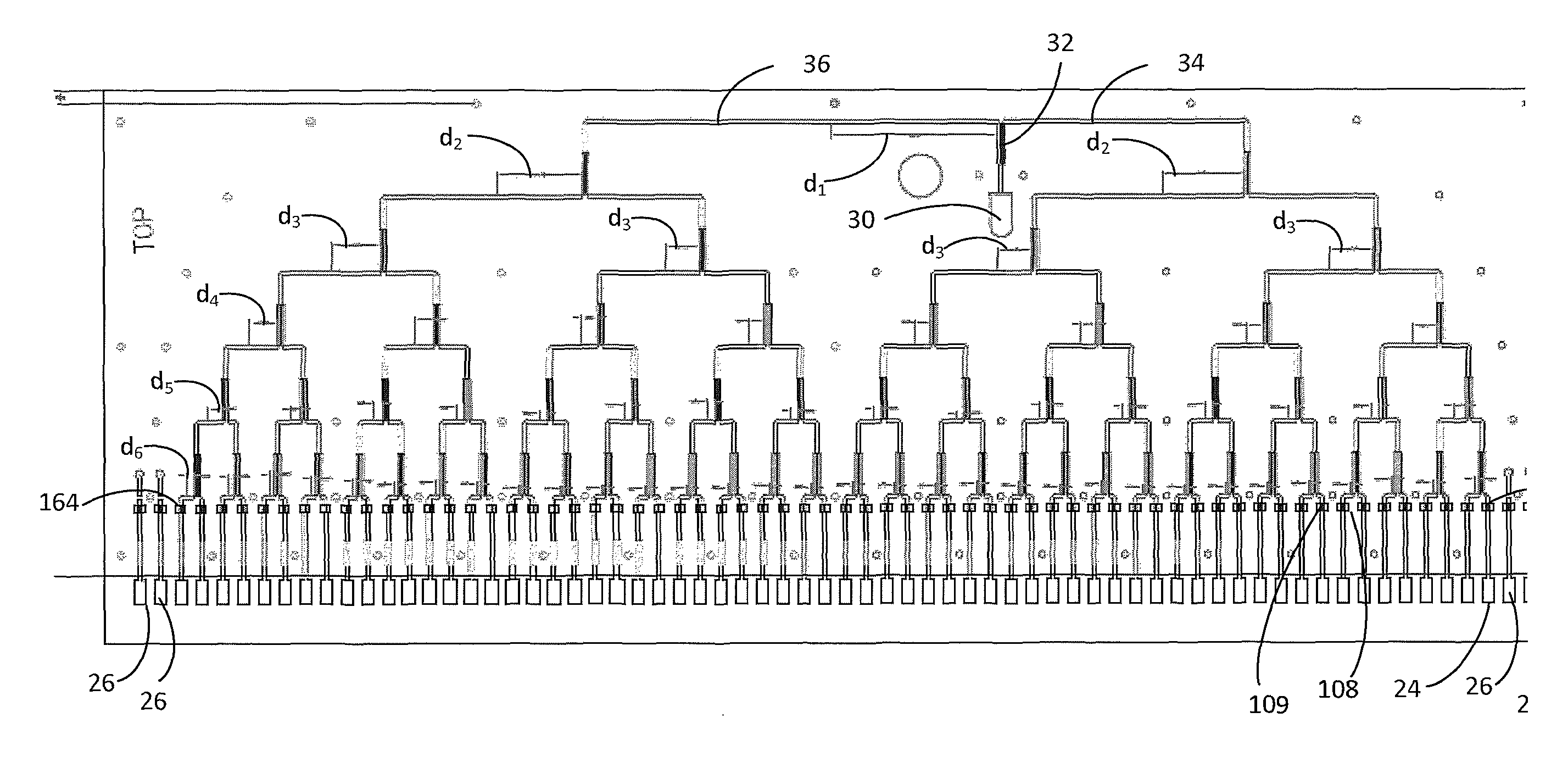
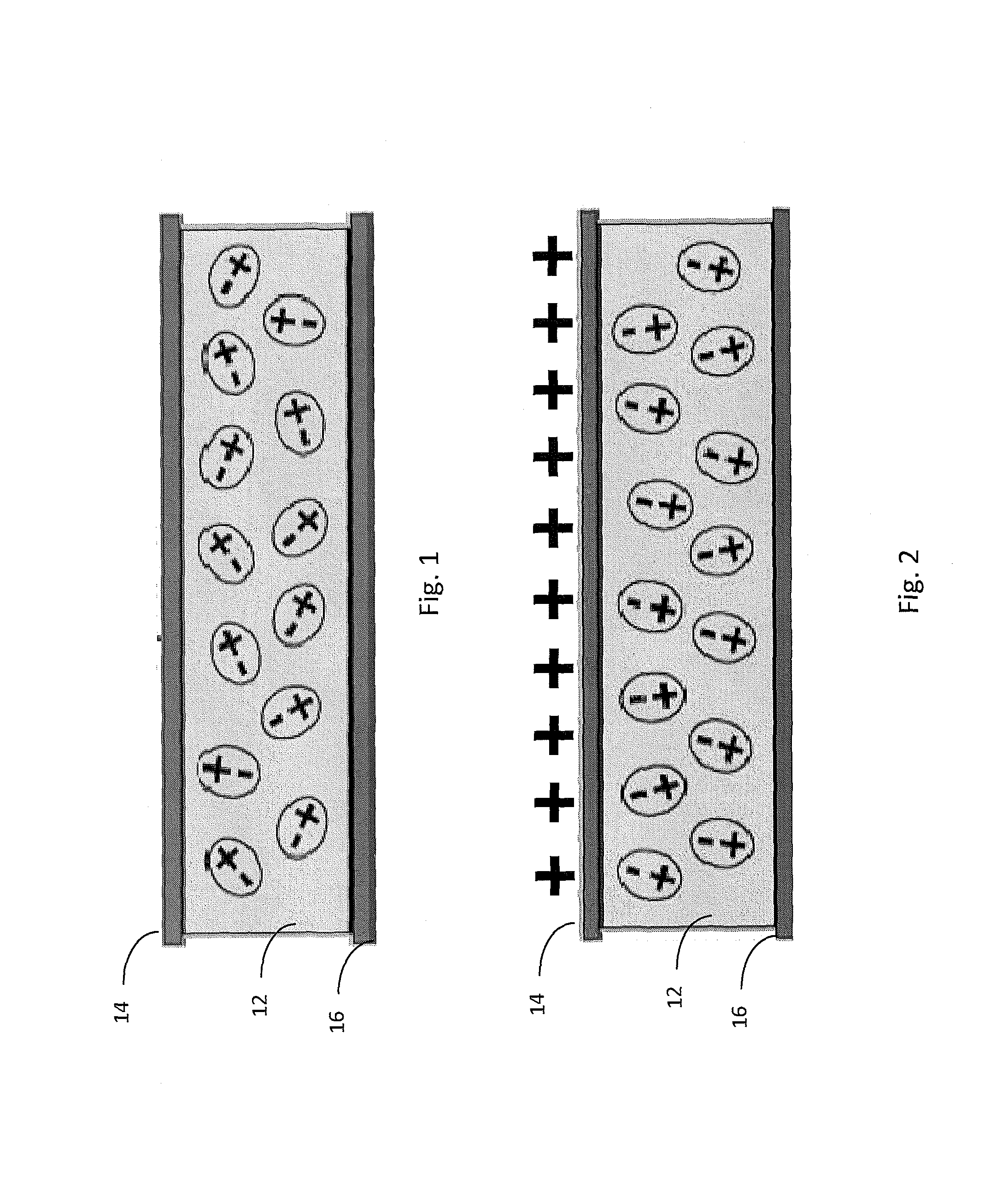
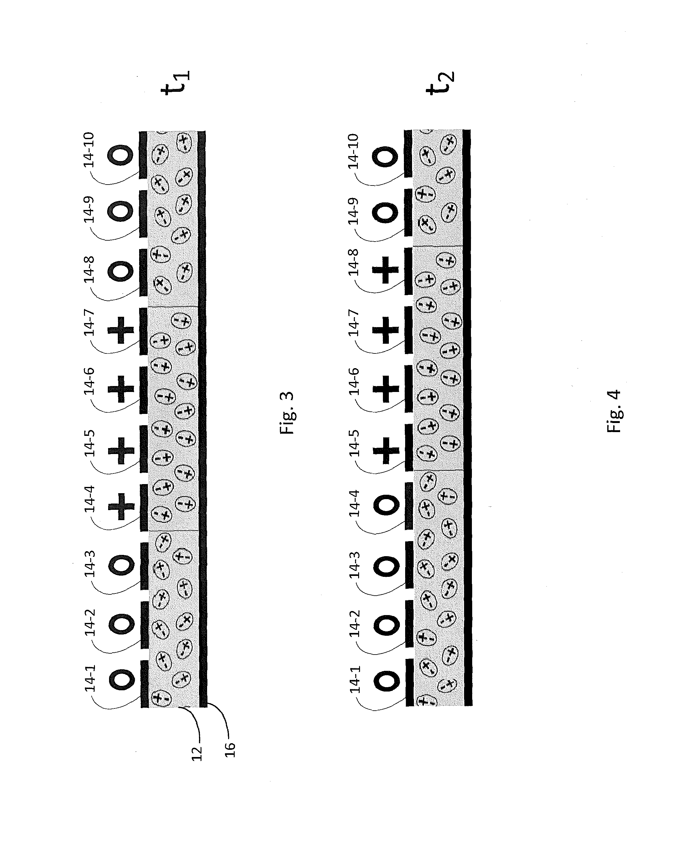
[0029]As explained in more detail below, the antenna may include a volume polarization current distribution radiator and a passive feed network. The volume polarization current distribution radiator comprises, in one example, a plurality of polarization devices, such as a plurality of electrodes, and a dielectric strip. The electrodes may be coupled above and a ground plate coupled below the dielectric. The dielectric has a finite polarization region created by selectively applying a positive voltage to one or more electrodes. The passive feed network is coupled to the polarization devices. The passive feed network receives a modulated Radio-Frequency (RF) signal and applies the RF signal according to...


PUM


Abstract

An antenna may include a volume polarization current radiator and a feed network. The volume polarization current radiator, includes a dielectric solid (such as a dielectric strip), and a plurality of closely-spaced excitation elements (24), each excitation element (24) being configured to induce a volume polarization current distribution in the dielectric solid proximate to the excitation element when a voltage is applied to the excitation element. The feed network is coupled to the volume polarization current radiator. The feed network also includes a plurality of passive power divider elements (32) and a plurality of passive delay elements (d1-d6) coupling the first port (30) and the plurality of second ports (108, 109, 164), the plurality of power divider elements (32) and the plurality of phase delay elements (d1-d6) being configured such that a radio-frequency signal that is applied to the first port (30) experiences a progressive change of phase as it is coupled to the plurality of second ports (108, 109, 164) so as to cause the volume polarization current distribution to propagate along the dielectric solid.

Description

STATEMENT REGARDING FEDERAL RIGHTS[0001]This invention was made in part with government support under Contract No. DE-AC52-06NA25396 awarded to Los Alamos National Security, LLC (LANS) by the U.S. Department of Energy and made in part under CRADA number LA11C10646 between CommScope, Inc. of North Carolina and LANS. The government has certain rights in the invention.[0002]This application claims priority to U.S. Provisional Application Ser. No. 61 / 738,836, filed Dec. 18, 2012, Pursuant to 35 U.S.C. §120.BACKGROUND OF INVENTION[0003]Passive feed networks have been known to be combined with discrete-element antenna arrays. These known antenna arrays typically have dipole or patch radiating elements. By providing a progressive, constant-difference phase shift to the point-source radiating elements, a beam pattern produced by the antenna may be steered from perpendicular with respect to the antenna face.[0004]Such known steerable arrays typically have from 5-15 discrete radiating element...

Claims


Application Information

Patent Timeline
Patent Type & Authority Patents(United States)
IPC IPC(8): H01Q1/50H01Q3/34H01Q3/30H01Q13/28H01Q21/00
CPCH01Q3/34H01Q3/30H01Q13/28H01Q21/0075
Inventor ARDAVAN, ARZHANGSINGLETON, JOHNLINEHAN, KEVIN E.ARDAVAN, HOUSHANGSCHMIDT-ZWIEFEL, ANDREA CAROLINE
Owner COMMSCOPE INC
Why Eureka
Try Eureka