
Bagged cement automatic bag-opening and discharging device for nuclear power station
A technology of unloading device and nuclear power plant, which is applied in the directions of packaging, transportation and packaging, and unsealing of objects, etc., which can solve the problems of inconvenient maintenance, high labor intensity, and high cost, and achieve convenient use and maintenance, good sealing effect, and simple structure Effect
Patent Information
- Authority / Receiving Office
- CN · China
- Current Assignee / Owner
- Publication Date
- 2013-02-13
Smart Images
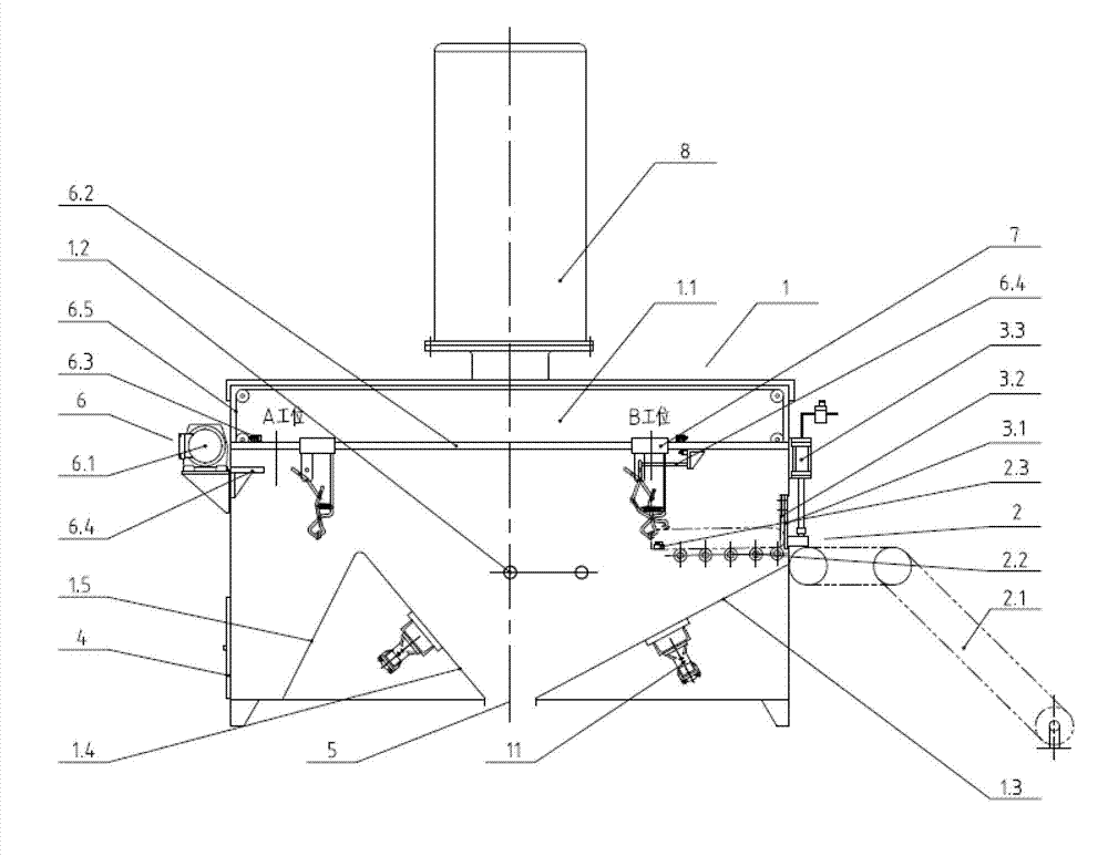
Figure 1 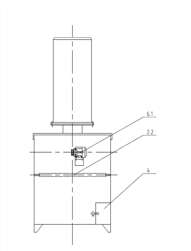
Figure 2 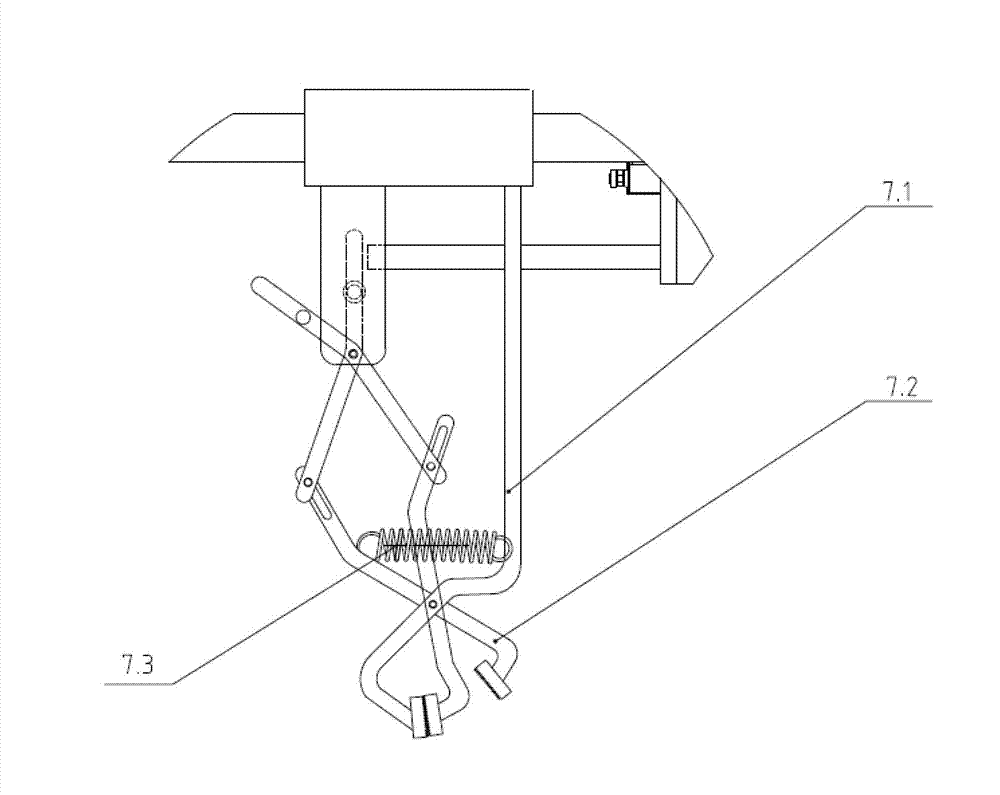
Figure 3
Abstract
Description
technical field
[0001] The invention relates to a bag opening and unloading device, in particular to an automatic bag opening and unloading device for bagged cement used in nuclear power plants. Background technique
[0002] During the operation of nuclear power plant waste treatment facilities, a large amount of cement needs to be used to solidify the waste. Manually opening bags and sending the cement to the mixing station is not only labor-intensive, it is easy to cause occupational diseases such as pneumoconiosis, and the dust will be radioactive after being irradiated. Serious polluted environment. The existing mechanical bag opening device has a large volume, a large floor space, and high cost, and it cannot completely separate the dry cement material and the cement bag when it works, and some crushed cement bags will be mixed into the dry cement material, causing the cement to be polluted. Chinese patent No. 200710134438.9 discloses a device for automatically opening...
Examples
Embodiment 1
[0020] The bagged cement automatic opening and unloading device for nuclear power plants shown in the figure includes a closed box 1, a conveying mechanism 2, a controller 9 and a start button 10. The closed box 1 is composed of a casing 1.1, a beam 1.2, a first inclined plate 1.3, The second slant plate 1.4 and the third slant plate 1.5 are composed. The conveying mechanism 2 is composed of a belt conveyor 2.1, a non-powered roller table 2.2 and a photoelectric sensor 2.3. The front end of the shell 1.1 is provided with a vertical lifting door 3.1, and the rear of the shell 1.1 The end face is provided with a cement bag recovery door 4, the bottom of the shell 1.1 is provided with a cement outlet 5, a cutting knife 3.2 is fixed on the inner surface of the vertical lift door 3.1, the vertical lift door 3.1 is driven by the power mechanism 3.3, and the unpowered roller table 2.2 is driven by It is composed of a plurality of mutually parallel rollers installed on both sides of th...
Embodiment 2
[0024] In the solution of Embodiment 1, the power mechanism 3.3 is a pneumatic actuator.
Embodiment 3
[0026] In the solution of embodiment 1 or embodiment 2, vibrators 11 are respectively provided on the lower surfaces of the first slant plate 1.3 and the second slant plate 1.4.