
Assembly process of jq900a bridge erecting machine
A technology of bridge erecting machine and technology, which is applied in the direction of erecting/assembling bridges, bridges, bridge construction, etc., and can solve the problems of long construction mileage, lack of construction equipment, and poor applicability, etc.
Patent Information
- Authority / Receiving Office
- CN · China
- Patent Type
- Patents(China)
- Current Assignee / Owner
- Publication Date
- 2015-12-02
- Estimated Expiration
- Not applicable · inactive patent
Smart Images
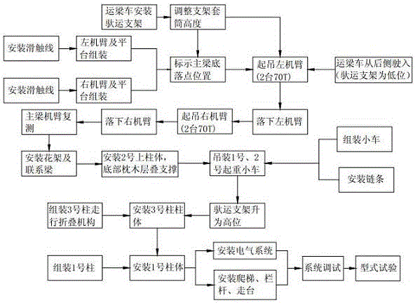
Figure 1 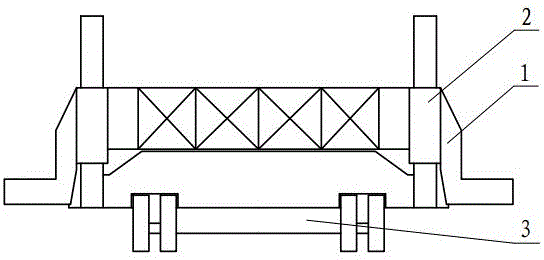
Figure 2 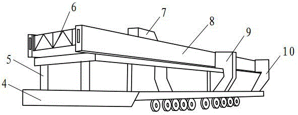
Figure 3
Abstract
Description
technical field
[0001] The invention relates to a bridge erecting machine assembly process, which belongs to the technical field of bridge construction. Background technique
[0002] Dedicated passenger line (high-speed railway) is the development direction of my country's railway construction and represents the development trend of China's railway technology. The prestressed concrete whole hole box girder has the advantages of high rigidity, good overall performance, fast construction speed, and easy quality assurance, so it has become the preferred bridge superstructure form for domestic high-speed railways and passenger dedicated lines.
[0003] At present, the domestic 900-ton box girder construction technology has been rapidly developed in recent years, but the domestic bridge erecting machine assembly construction technology has not been innovated. The technology currently used is that after the ground machine arm is assembled and formed, it is lifted to the carrying ...
Examples
Embodiment Construction
[0028] According to attached figure 1 It can be seen that the present invention specifically relates to a JQ900A bridge erecting machine assembly process, which belongs to the technical field of bridge construction.
[0029] The assembly process of JQ900A bridge erecting machine is as follows:
[0030] 1) According to the direction of the beam erection, first assemble the left and right main beams 8 and the supporting platform, and then install the carrying bracket 1 on the beam transporting vehicle and adjust the height through the bracket sleeve 2;
[0031] 2) Adjust the height of the support sleeve 2 so that the cross arm of the carrying support 1 is 2 meters away from the ground, that is, the lower position, and fix the support sleeve 2 with a pin;
[0032] 3) According to the structural shape and size of the main beam 8, mark the landing point position on the bottom surface of the main beam 8 and the bracket ear;
[0033] 4) Through the cooperation of two 70-ton cranes,...