
Domestic appliance for clothes drying
A technology for household electrical appliances and clothes, applied in the field of household electrical appliances for drying clothes, can solve the problems of single drying airflow direction, long drying time, high cost of drying machines, etc., and achieve uniform drying of clothes, simple structure, Easy-to-use effects
Patent Information
- Authority / Receiving Office
- CN · China
- Patent Type
- Applications(China)
- Current Assignee / Owner
- Publication Date
- 2018-05-29
- Estimated Expiration
- Not applicable · inactive patent
Smart Images
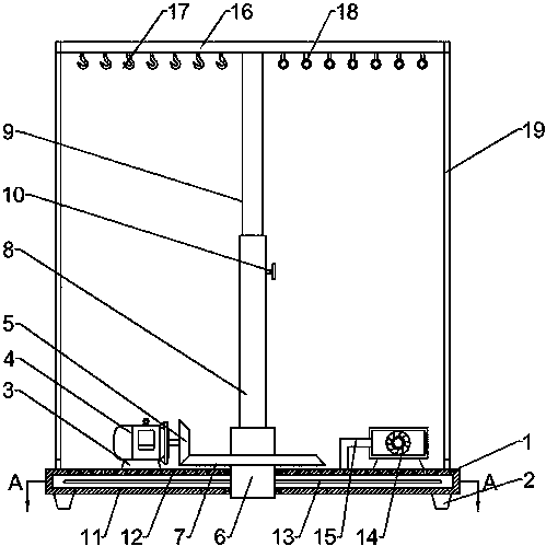
Figure 1 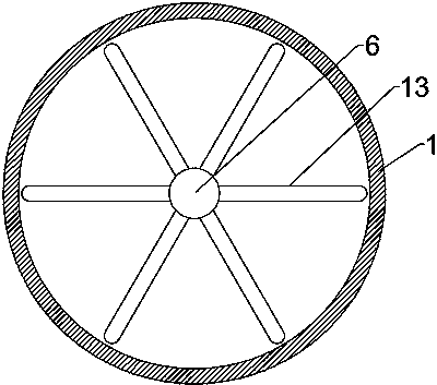
Figure 2
Abstract
Description
Technical field
[0001] The invention relates to a household appliance, in particular to a household appliance for drying clothes. Background technique
[0002] The southern climate is warm and humid, with strong sunlight and a lot of rain. There is a long rainy season before the summer. In the vast areas of southern China, the climate is humid and warm, with more precipitation and strong sunshine. South China Sea, Guangdong, Guangxi, Hainan and Nanhai, south of the Tropic of Cancer In other places, the tropical climate is obvious. It often rains when entering the rainy season, and due to the high humidity of the air, clothes are usually difficult to dry naturally, and when the rain is continuous, they often encounter their clothes being wet. Therefore, it is necessary to manually treat the clothes to speed up the drying process of the clothes.
[0003] The existing clothes dryer is a type of washing machine, which is generally used to remove moisture from clothing and other texti...
Examples
Embodiment Construction
[0017] The technical solution of this patent will be described in further detail below in conjunction with specific embodiments.
[0018] See Figure 1-2 , A household appliance for clothes drying, comprising a fixed base 1, a motor base 3 is fixedly connected to the upper left side of the fixed base 1, a motor 4 is fixedly connected to the upper side of the motor base 3, and the output end of the motor 4 is fixedly connected There is a driving bevel gear 5, the upper and middle part of the fixed base 1 is rotatably connected with a fixed shaft 6, and the upper and outer sides of the fixed shaft 6 are fixedly connected with a driven bevel gear 7, and the driven bevel gear 7 meshes with the driving bevel gear 5. The fixed shaft 6 An outer sleeve 8 is threaded on the upper side, and a telescopic rod 9 is slidably connected above the outer sleeve 8. A fixing bolt 10 is threaded on the outer side of the outer sleeve 8 and the fixing bolt 10 passes through the outer sleeve 10 to fit w...