
Press-fitting device of battery cover cap
A technology for press-fitting devices and battery covers, which is applied to workpiece clamping devices, metal processing, metal processing equipment, etc., can solve the problems of high manufacturing cost, difficult maintenance and calibration for operators, and difficult maintenance, so as to achieve stable and easy structural transformation The effect of taking out and stabilizing adsorption
Patent Information
- Authority / Receiving Office
- CN · China
- Current Assignee / Owner
- Publication Date
- 2018-10-09
Smart Images
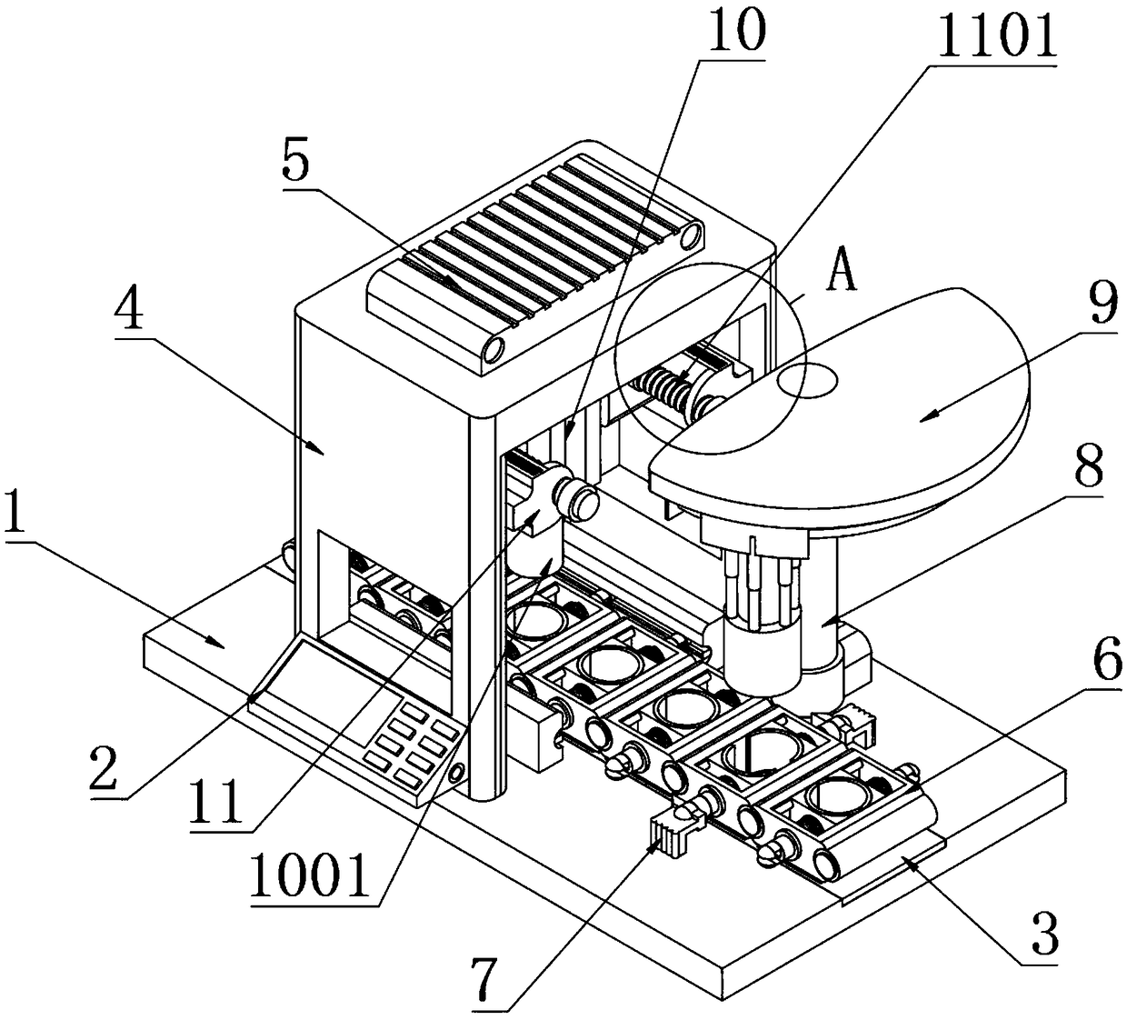
Figure 1 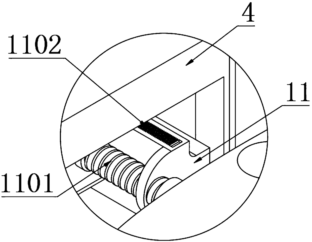
Figure 2 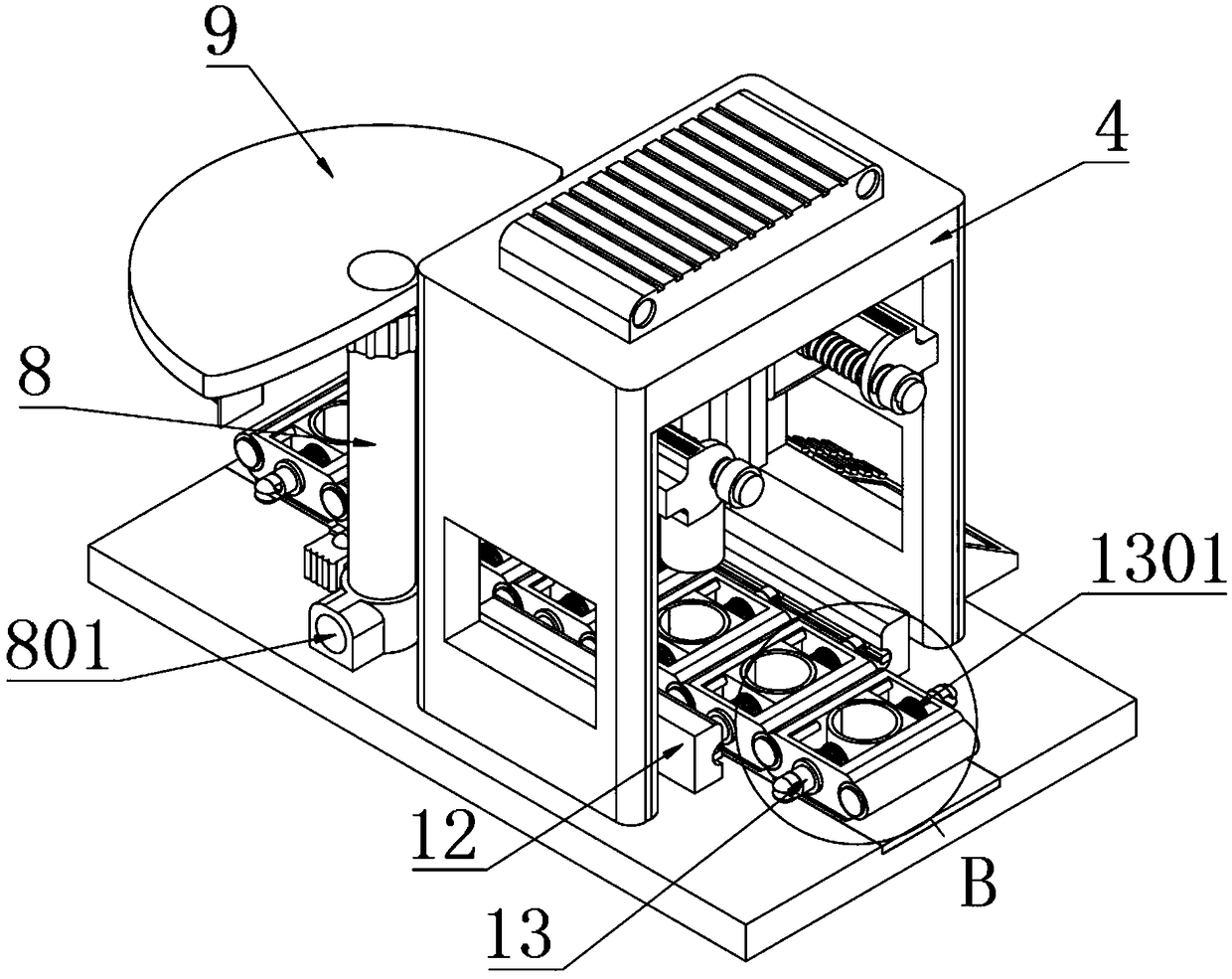
Figure 3
Abstract
Description
technical field
[0001] The invention belongs to the technical field of battery electronic processing, and more specifically relates to a battery cap press-fitting device. Background technique
[0002] During the production process of the battery, it is necessary to ensure that the cap of the battery is pressed in place before the battery sealing process. At present, the method of pressing the cap is mainly manual pressing, which is unstable and uneven, and the sealing ring is easy to be crushed when the product is sealed, causing problems such as battery leakage and short circuit.
[0003] Some mechanical press-fitting, such as a patented battery cap pressing device (CN2017205571840U), is set between the battery cap press-fitting process and the battery sealing process to ensure that the battery cap is pressed in place; using the laser sensor switch principle, Combining electrical and mechanical design related methods to achieve automation effects, and has the characteristi...
Examples
Embodiment
[0050] as attached figure 1 to attach Figure 11 Shown:
[0051] The invention provides a battery cap press-fitting device, which includes an operation table 1, a control panel 2, a conveyor belt 3, a press-fit stand 4, a PLC controller 5, a clamping disc 6, a hinge shaft 601, a guide rail 602, a limit column 603, an expansion Block 7, displacement block 701, support column 8, vacuum pump connector 801, stroke plate 9, arc hanging rail 901, electric push rod 902, hydraulic electric cylinder 10, press-fitting head 1001, clamping block 11, screw screw 1101, precision ruler 1102, guide body 12, guide groove 1201, correction plate 1202, automatic compression column 13, spring 1301, auxiliary shift head 1302, fixing bolt 1303, fixing plate 14, positioning groove 1401, chute 1402, suction head 15. Adsorption sleeve 1501, miniature electric cylinder 16, air pipe 17, rotating disk 1701, slider 18 and adjustment block 19, the conveyor belt 3 is arranged on the console 1; the front an...