
Redundant control system and method applied to three-phase solid-state transformer
A technology of solid-state transformer and redundant control, which is applied in the direction of control/regulation systems, instruments, and regulation of electrical variables, etc. It can solve problems such as inrush current, affecting the safety of equipment and systems, and increasing the cost of equipment redundancy, so as to achieve fast dynamic Response, redundant cost saving, design and production cost saving effects
Patent Information
- Authority / Receiving Office
- CN · China
- Patent Type
- Applications(China)
- Current Assignee / Owner
- Publication Date
- 2019-05-24
- Estimated Expiration
- Not applicable · inactive patent
Smart Images
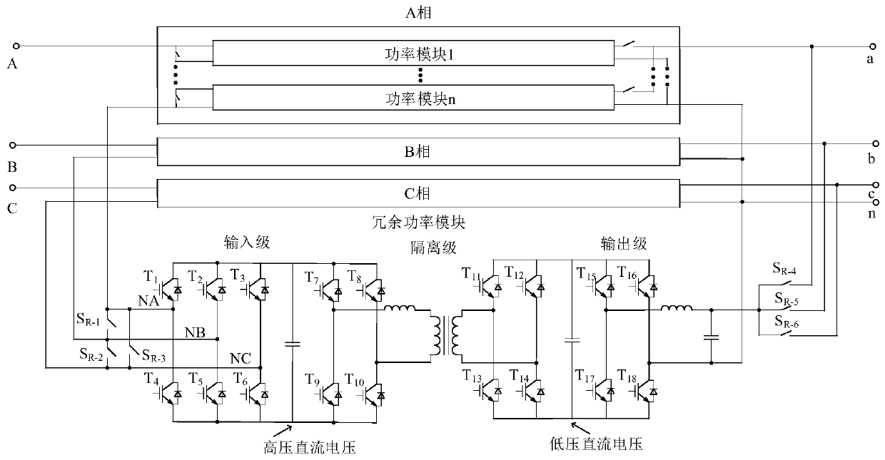
Figure 1 
Figure 2 
Figure 3
Abstract
Description
technical field
[0001] The invention belongs to the technical field of AC-DC interface solid-state transformers in distribution networks, in particular to a redundant control system and method applied to three-phase solid-state transformers. Background technique
[0002] In recent years, the application of power electronic devices in all aspects of the power system has become more and more extensive, and the power electronic power system has become a foreseeable trend in the development of the future power grid. The continuous growth of energy demand and the increasingly serious problems of environmental pollution have promoted the adjustment of energy structure centered on electricity and characterized by clean energy. The development and utilization of clean energy has become the common choice of major countries in the world. In the process of urban distribution network with power electronics, AC-DC interface power electronic equipment occupies a large proportion. Formal ...
Examples
Embodiment Construction
[0049] Embodiments of the present invention are described in further detail below in conjunction with the accompanying drawings:
[0050] A redundant control system applied to a three-phase solid-state transformer, characterized in that it includes: its topology includes a plurality of power modules and a redundant power module in the three phases A, B, and C, and a plurality of power modules adopt The input stage is connected in series and cascaded, and the output stage is connected in parallel and cascaded; in addition, the three phases A, B, and C share a redundant power module, which is divided into three parts: input stage, isolation stage and output stage. Its input stage is connected to three high-voltage semi-controlled bypass switches S R_1 -S R_3 , the output stage is connected to three low-voltage full-control switches S R_4 -S R_6 ; The input stage is a rectifier unit composed of 6 switching tubes, and the output stage is an inverter unit composed of 4 switching...