
A small size directional drilling equipment
A technology of directional drilling and small size, applied in the direction of stone processing equipment, work accessories, manufacturing tools, etc., can solve the problems of inability to realize directional drilling and the position of the drill bit of the electric drill, and achieve the position adjustment process and the drilling process easily. Convenience, easy operation, easy and convenient transportation
Patent Information
- Authority / Receiving Office
- CN · China
- Patent Type
- Patents(China)
- Current Assignee / Owner
- Publication Date
- 2021-11-26
Smart Images
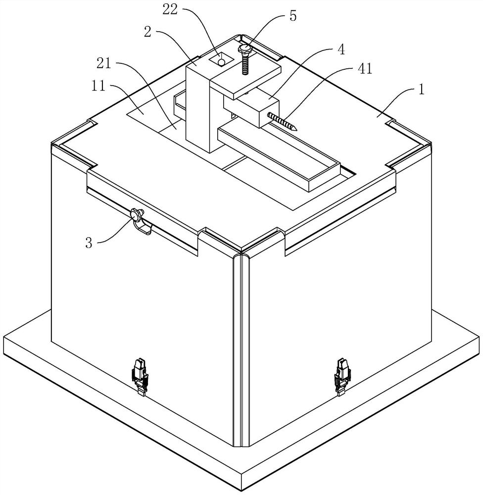
Figure 1 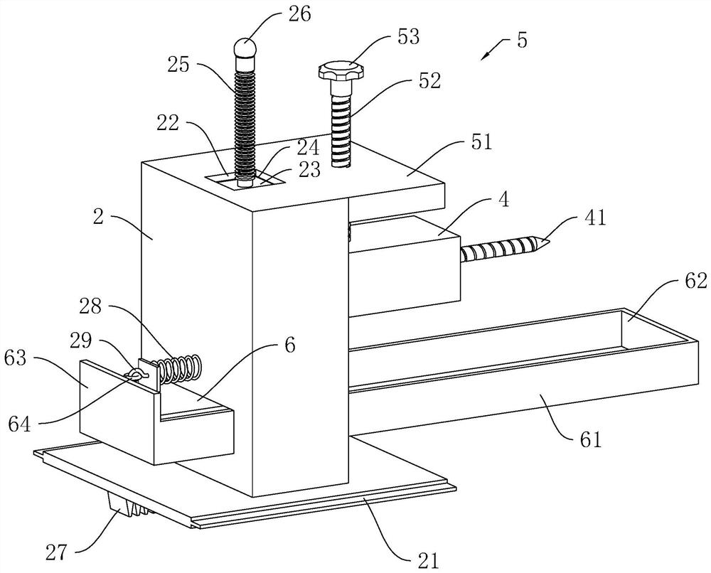
Figure 2 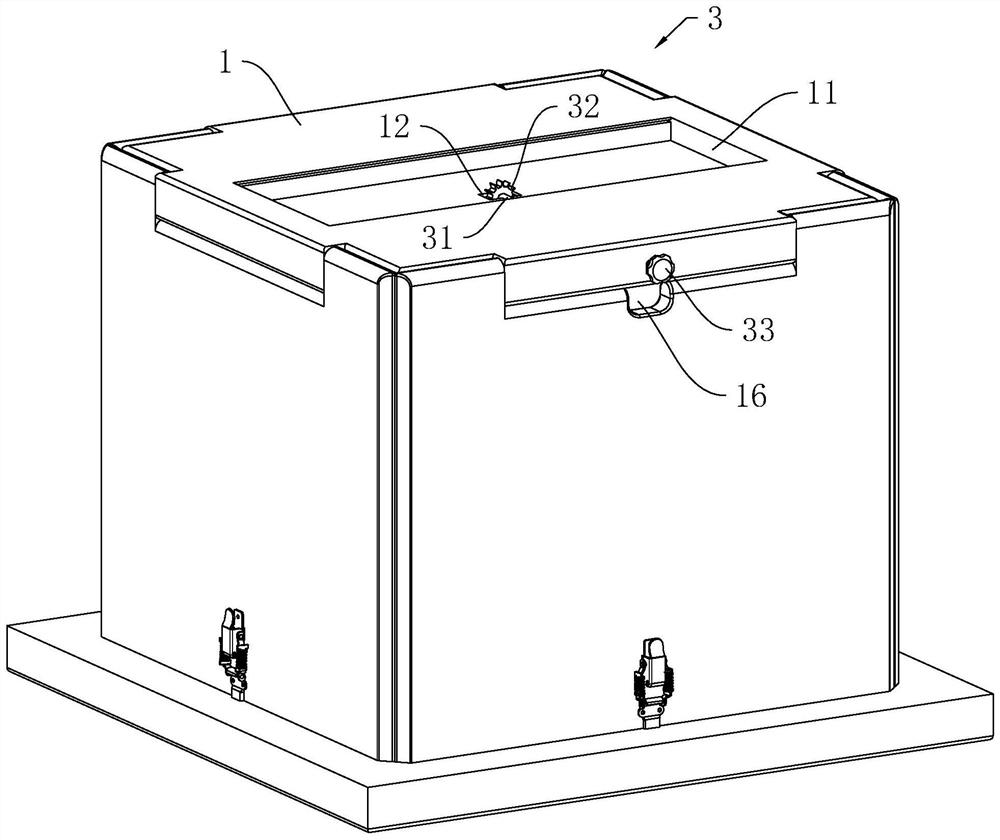
Figure 3
Abstract
Description
technical field
[0001] The invention relates to the field of drilling equipment, in particular to a small-sized directional drilling equipment. Background technique
[0002] The inspection well is the underground space for the transfer and control of urban underground pipelines. In the city, all public water supply, sewage channels, telephone lines, and optical fiber networks may be connected through the underground passage under the inspection well, which is an indispensable part of urban buildings. .
[0003] When laying pipelines in the inspection shaft, it is often necessary to carry out drilling operations to the side wall of the inspection shaft. Because the space of the inspection shaft is relatively narrow, when drilling, the manual hand-held electric drill is often used to drill holes. However, when the hand-held electric drill is used for drilling, the position of the drill bit of the electric drill often shakes, so directional drilling cannot be realized, which n...
Examples
Embodiment Construction
[0035] The present invention will be described in further detail below in conjunction with the accompanying drawings.
[0036] Such as figure 1As shown, a small-sized directional drilling equipment includes a base 1, a support seat 2 is vertically arranged on the base 1, a long slider 21 is provided on the lower end surface of the support seat 2, and a strip-shaped slider 21 is provided on the upper end surface of the base 1. There is a chute 11 for the sliding block 21 to slide, and the base 1 is provided with a first driving mechanism 3 for driving the sliding block 21 and the supporting seat 2 to slide horizontally.
[0037] Such as figure 1 As shown, the side wall of the support base 2 is vertically slidably connected with the mounting base 4, the side of the mounting base 4 facing away from the support base 2 is provided with a drill bit 41, and the support base 2 is provided with a tool for driving the vertical sliding of the mounting base 4. The second drive mechanism...