
Optimal voltage boundary overmodulation method for permanent magnet synchronous motor without electrolytic capacitor drive
A permanent magnet synchronous motor and electrolytic capacitor technology, which is used in motor generator control, electromechanical brake control, AC motor control, etc., can solve problems such as back-off and output voltage vector phase jump, avoid jumping, and ensure voltage utilization. rate effect
Patent Information
- Authority / Receiving Office
- CN · China
- Patent Type
- Patents(China)
- Current Assignee / Owner
- Publication Date
- 2021-03-09
Smart Images
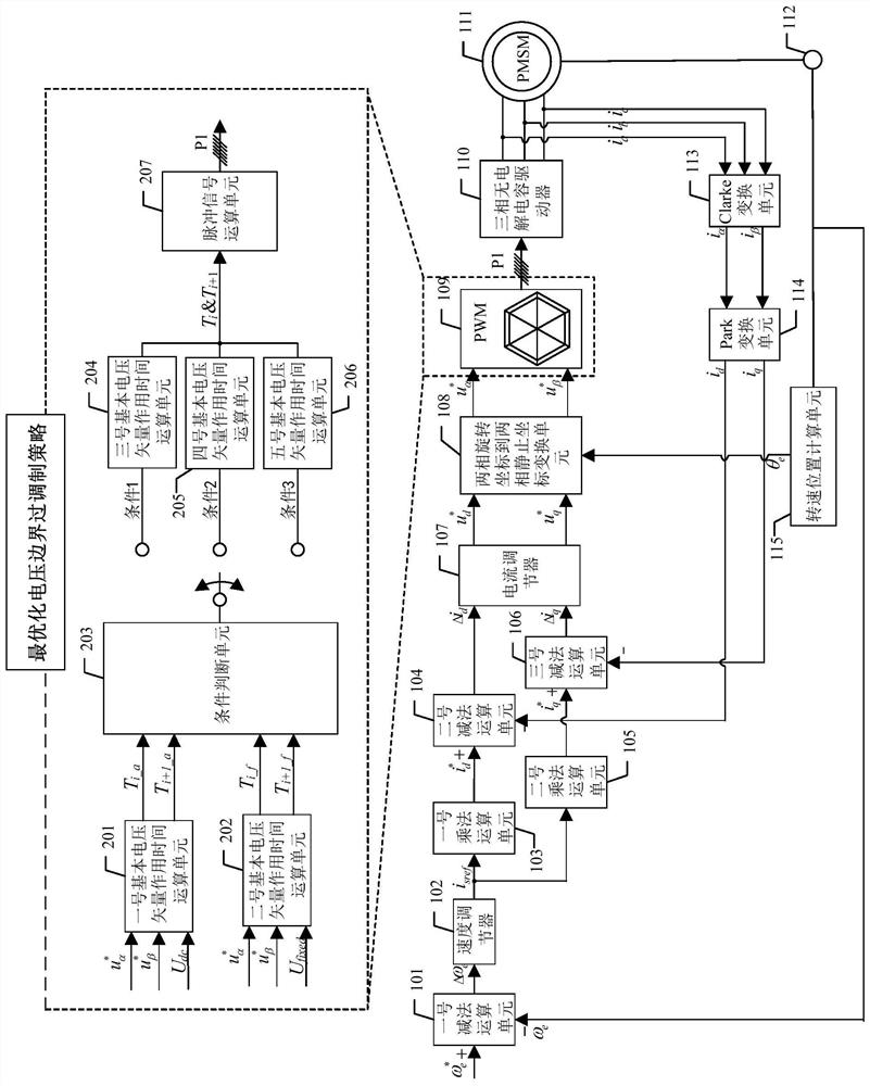
Figure 1 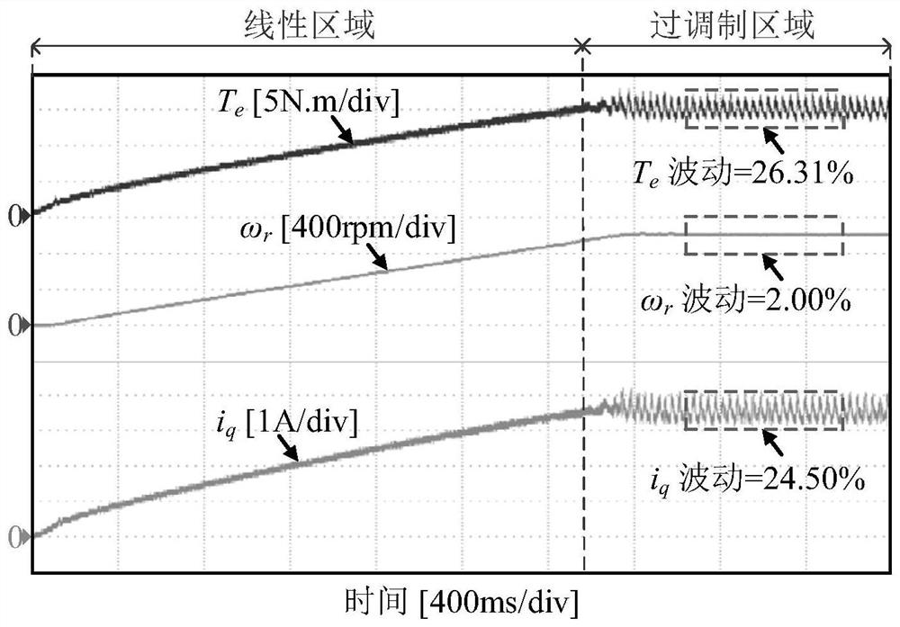
Figure 2 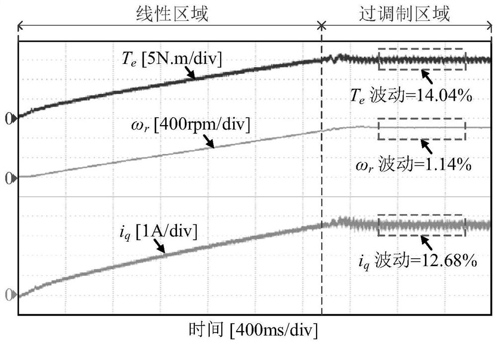
Figure 3
Abstract
Description
technical field
[0001] The invention relates to a voltage boundary optimization overmodulation method for a non-electrolytic capacitor driver of a permanent magnet synchronous motor, and belongs to the technical field of motor control. Background technique
[0002] Permanent magnet synchronous motor has the advantages of high power density, high torque density, and low cost, and it has more and more applications in the fields of industry and home appliances. In the traditional motor drive topology, large-capacity electrolytic capacitors are often used on the DC side to ensure the stability of the DC bus voltage, but the life of the electrolytic capacitor is greatly affected by the ambient temperature and current ripple. The use of film capacitors can significantly improve the life and reliability of the motor drive system. The motor drive system that replaces the electrolytic capacitors on the DC side with film capacitors is called a motor drive system without electrolytic c...
Examples
specific Embodiment approach 1
[0033] Specific implementation mode 1. Combination figure 1 As shown, the present invention provides a permanent magnet synchronous motor non-electrolytic capacitor driver voltage boundary optimization overmodulation method, comprising the following steps:
[0034] Step 1: Collect and process the actual three-phase current of the three-phase non-electrolytic capacitor driver to obtain the α-axis voltage command u α * and β-axis voltage command u β * ;
[0035] Step 2: Use the No. 1 basic voltage vector action time operation unit 201 to command the α-axis voltage u α * , β-axis voltage command u β * and the actual voltage U output by the three-phase electrolytic capacitor driver dc Perform calculations to obtain the first expected action time T of two adjacent basic voltage vectors in the permanent magnet synchronous motor vector control i_a , T i+1_a ; Simultaneously, the No. 2 basic voltage vector action time operation unit 202 is used to command the α-axis voltage ...
Embodiment
[0056] Embodiment: The effectiveness of the optimal voltage boundary overmodulation strategy proposed by the present invention is verified on the electrolytic capacitor permanent magnet synchronous motor drive system platform. The parameters of the experimental platform are set as follows: the grid voltage is 380V, the grid frequency is 50Hz, the DC bus capacitor is a film capacitor with a capacitance value of 50μF, the d-axis inductance of the motor is 35mH, the q-axis inductance is 54mH, the rotor flux linkage is 0.86Wb, and the number of rotor pole pairs is 3, the rated power is 2.2kW, the rated speed is 1000r / min, and the stator resistance is 2.75Ω. All control algorithms in the experiment are completed in ARM STM32F103. The switching frequency and the current and voltage sampling value update frequency are both set to 6kHz.
[0057] Depend on figure 2 and image 3 It can be seen from the comparison that the control method of the present invention makes the torque fluc...