
Low-power-consumption redundant current sharing circuit based on PMOS
A low-power, redundant technology, applied in emergency protection circuit devices, circuit devices, emergency protection circuit devices for limiting overcurrent/overvoltage, etc., can solve problems such as high power supply requirements
Patent Information
- Authority / Receiving Office
- CN · China
- Patent Type
- Applications(China)
- Current Assignee / Owner
- Publication Date
- 2020-07-31
Smart Images
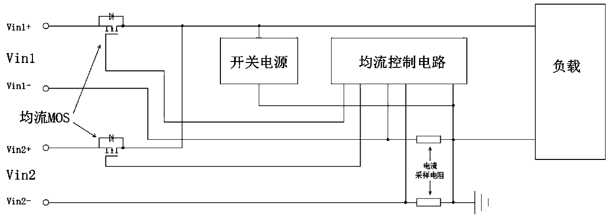
Figure 1 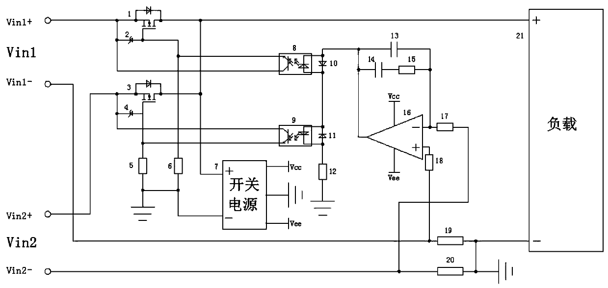
Figure 2 
Figure 3
Abstract
Description
technical field
[0001] The invention relates to the technical field of power electronics, in particular to a PMOS-based low power consumption redundant current sharing circuit. Background technique
[0002] Circuit: A conductive circuit composed of metal wires and electrical and electronic components is called a circuit. Adding a power supply to the input end of the circuit causes a potential difference at the input end, and the circuit can work when it is connected. The existence of current can be tested by some instruments, such as voltmeter or ammeter deflection, light bulb lighting, etc.; according to the nature of the current flowing, it is generally divided into two types: the circuit through which direct current passes is called "DC circuit", and the circuit through which alternating current passes The circuit is called an "AC circuit".
[0003] The bridge arm of the MMC flexible direct current transmission converter valve is composed of many power units in series. ...
Examples
Embodiment 1
[0037] see Figure 1-2 , a PMOS-based low-power redundant current sharing circuit, including Vin1 and Vin2, the positive terminal of Vin1 is respectively connected to the drain of the first current sharing MOS1, the cathode of the first Zener diode 2 and the first drive optocoupler 8 The collector of the secondary side, the positive terminal of Vin2 are respectively connected to the drain of the second current sharing MOS3, the cathode of the second Zener diode 4 and the secondary collector of the second driving optocoupler 9, and the gate of the first current sharing MOS1 They are respectively connected to the anode of the first zener diode 2, the emitter of the secondary side of the first drive optocoupler 8 and the upper end of the second drive resistor 6, and the gate of the second current sharing MOS3 is respectively connected to the anode of the second zener diode 4 1. The secondary emitter of the second drive optocoupler 9 is connected to the upper end of the first driv...