
Medical cryoablation catheter
A technology for ablation catheters and sheaths, applied in the medical field, can solve the problems of large cooling capacity consumption, high risk factor, and slow cooling rate, and achieve the effects of uniform cooling capacity distribution, improved safety, and control of cooling capacity dispersion
Patent Information
- Authority / Receiving Office
- CN · China
- Patent Type
- Applications(China)
- Current Assignee / Owner
- Publication Date
- 2020-12-08
Smart Images
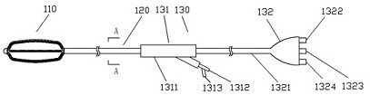
Figure 1 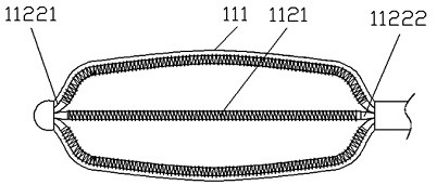
Figure 2 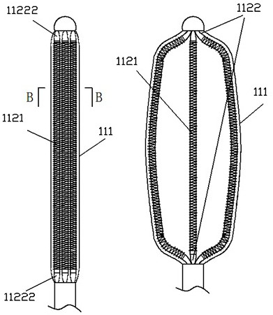
Figure 3
Abstract
Description
technical field
[0001] The invention belongs to the medical field, in particular to a medical cryoablation catheter. Background technique
[0002] Patent No.: CN201520045658 discloses a cryoablation balloon catheter with a guide wire lumen. The basic principle is to block the renal artery through the balloon to block the blood flow, and then release the cold energy from the helical structure in the middle area of the balloon, thereby To achieve ablation of the renal artery, although the catheter can cryoablate the renal artery, it is necessary to block the renal artery and block the blood flow to improve the freezing performance of the catheter. If the blocking time is too long, it may cause renal ischemia Sexual necrosis.
[0003] Most of the existing cryoablation products are structures in which the refrigerant is directly injected into the balloon or diffused from the center of the cold source in the balloon, but the structure of directly injecting refrigerant into the...
Examples
Embodiment Construction
[0026] In order to make the technical solution of the present invention clearer, the present invention will be further described below in conjunction with the accompanying drawings. Any solution obtained by equivalent replacement and conventional reasoning of the technical features of the technical solution of the present invention falls within the protection scope of the present invention.
[0027] Such as figure 1 The shown medical cryoablation catheter includes a delivery unit 120 and a freezing unit 110, wherein the delivery unit 120 includes a sheath tube 121 and a circulation circuit 122 arranged axially in the sheath tube 121, and the freezing The unit 110 is set at the distal end of the sheath tube 121, that is, the leftmost end of the delivery unit 120. The freezing unit 110 includes a balloon 111 and a directional bender 1121. The distal part of the circulation loop 122 is set at the In the balloon 111, the distal end of the circulation loop 122 is fixedly connected ...