
Pay-off arm for high-speed rail cable laying
A cable and high-speed rail technology, which is applied in the field of pay-off arms for high-speed rail cable laying, can solve problems such as inability to solve the problem of cable and cable guidance, and achieve the effect of improving construction efficiency
Patent Information
- Authority / Receiving Office
- CN · China
- Current Assignee / Owner
- Publication Date
- 2022-01-14
Smart Images
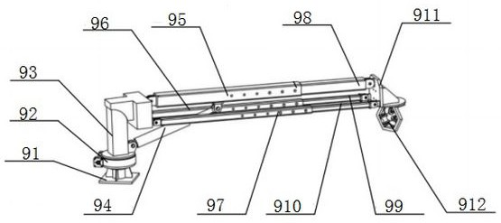
Figure 1 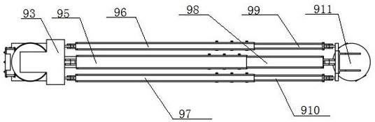
Figure 2
Abstract
Description
technical field
[0001] The invention belongs to the technical field of high-speed rail four-electric project construction, and in particular relates to a pay-off arm for laying high-speed rail cables. Background technique
[0002] The cables in the construction of the high-speed railway four-power project mainly include signal cables and power cables. The cable laying has the characteristics of difficult transportation, heavy cable reel weight, and long laying mileage. The laying process has high requirements for cable protection and construction quality control. Strict, the current general practice is still mainly manpower, use simple flatbed trucks to transport cable reels, and cooperate with pay-off pulleys for construction operations. The laying of each cable requires 20-50 people, which requires a lot of people and low construction efficiency. , the overall construction technology is not high. The mechanical laying equipment developed by individual construction units h...
Examples
Embodiment Construction
[0012] The present invention will be described in further detail below in conjunction with the accompanying drawings and specific embodiments.
[0013] According to attached figure 1 to attach figure 2 A pay-off arm for high-speed rail cable laying shown includes a base 91, the top of which is connected to a slewing support 92 controlled by a hydraulic control system, and the slewing support 92 can rotate around the base 91, changing the arm The rotation angle of the body, the end of the slewing support 92 away from the base 91 is connected to the turntable 93, the bottom side of the turntable 93 is hinged to one end of the luffing cylinder 94, the other end of the luffing cylinder 94 is connected to the first basic arm 95, and the luffing cylinder 94 is connected to the first basic arm 95. A basic arm 95 is connected, and the pitch angle of the arm body can be adjusted by changing the telescopic length of the luffing cylinder 94. During the pitching process, the expansion a...