
Steel-aluminum combined chain wheel
A sprocket, steel-aluminum technology, applied in belts/chains/gears, hoisting devices, components with teeth, etc., can solve the problems of low transmission deformation, inconsistent wear degree, and inability to fully utilize the output power. The transmission is smooth and stable, the effect of use is guaranteed, and the effect of adjusting the position of the gear teeth is convenient
Patent Information
- Authority / Receiving Office
- CN · China
- Patent Type
- Applications(China)
- Current Assignee / Owner
- Publication Date
- 2022-07-29
Smart Images
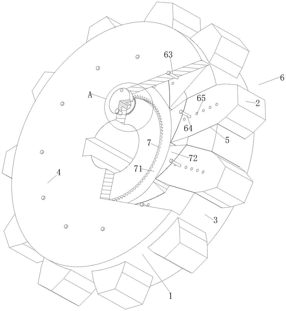
Figure 1 
Figure 2 
Figure 3
Abstract
Description
technical field
[0001] The invention relates to the technical field of sprockets, in particular to a steel-aluminum composite sprocket. Background technique
[0002] The sprocket is the embodiment of power transmission and drive in the industry. It requires good strength, wear resistance and low transmission deformation. The existing industrial drive sprockets are roughly divided into two types. One type of sprocket is processed from steel, and its rigidity It has good strength and can meet the requirements of industrial driving, but it is heavy, causing part of the kinetic energy to be consumed in the rotation of the pulling sprocket, so that the output power cannot be fully utilized; the other sprocket is processed from aluminum alloy. The weight of the sprocket is light, but the hardness and strength are not as good as the steel sprocket, and the service life is short; therefore, the outer ring of the sprocket is usually made of steel material, which has high strength; th...
Examples
Embodiment approach
[0042] As an embodiment of the present invention, one end of the No. 1 bolt 64 located in the No. 2 fixing groove 65 is not provided with threads.
[0043] When working, the staff screw the No. 1 bolt 64 during maintenance or maintenance, so that the No. 1 bolt 64 is detached from the No. 1 thread groove 63 and the No. 2 fixing groove 65; Pull the gear tooth 2 after the second fixing slot 65, so that the gear tooth 2 slides in the sliding slot 5, and the length of the gear tooth 2 exposed to the wheel body 1 increases. 63 is aligned with the corresponding No. 2 fixing groove 65 on the gear tooth 2, and then screw the No. 1 bolt 64 into the No. 1 thread groove 63; the staff continues to screw the No. 1 bolt 64, so that the No. 1 bolt 64 enters the corresponding In the No. 2 fixing groove 65, the fixing of the gear teeth 2 is completed; after the staff adjusts and fixes the positions of all the gear teeth 2, the maintenance and maintenance of the present invention are completed;...