
Ion detection arrangement
a detection arrangement and ion technology, applied in the field of mass spectrometers, can solve the problems of inflexible existing systems when dealing with ions with a range of different mass, and difficulty in providing both high and low resolution mass spectra using the same instrumen
Patent Information
- Authority / Receiving Office
- US · United States
- Current Assignee / Owner
- Publication Date
- 2013-05-09
Smart Images
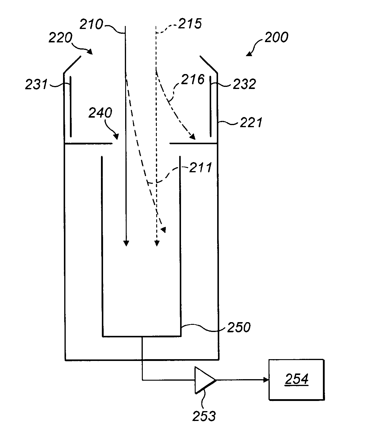
Figure 1 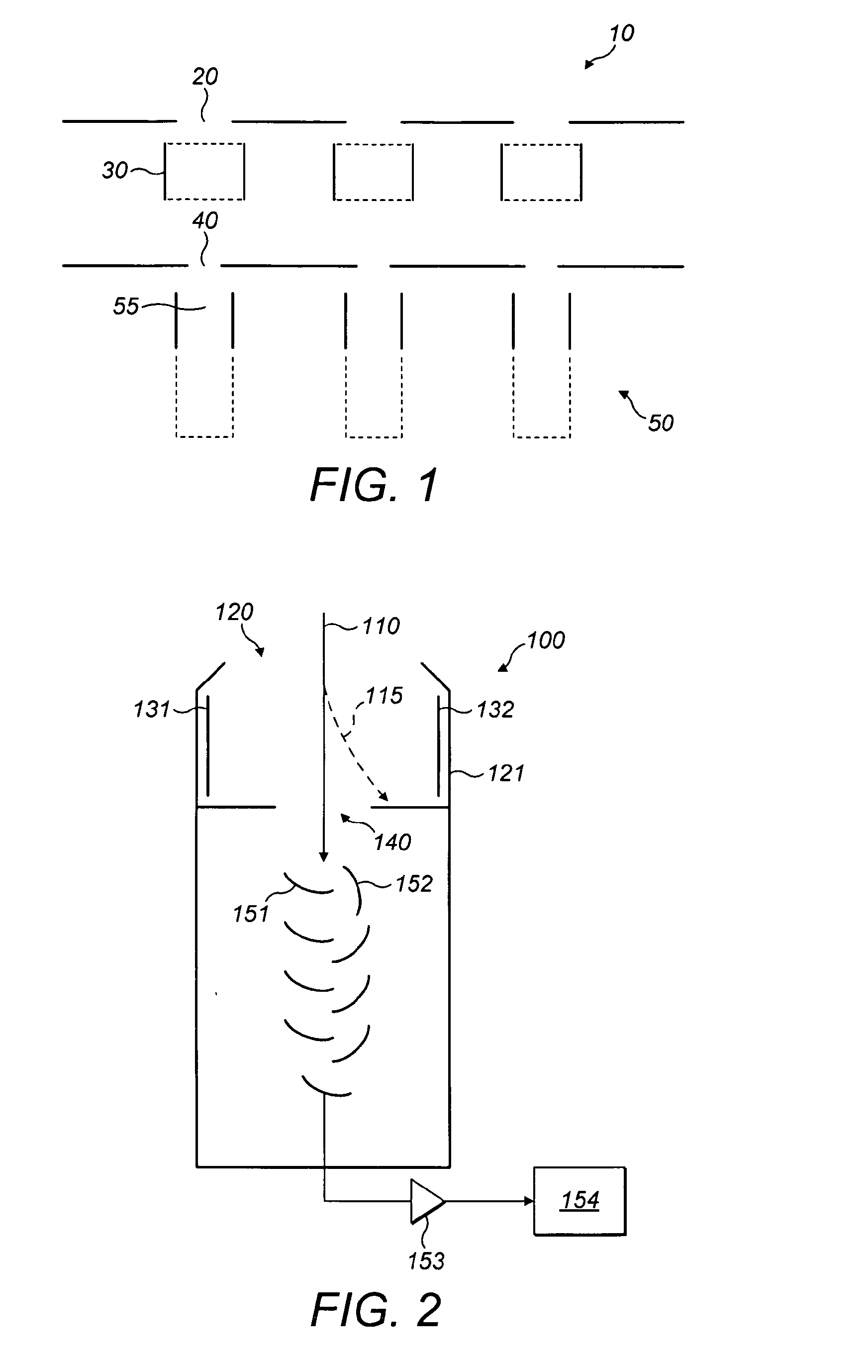
Figure 2 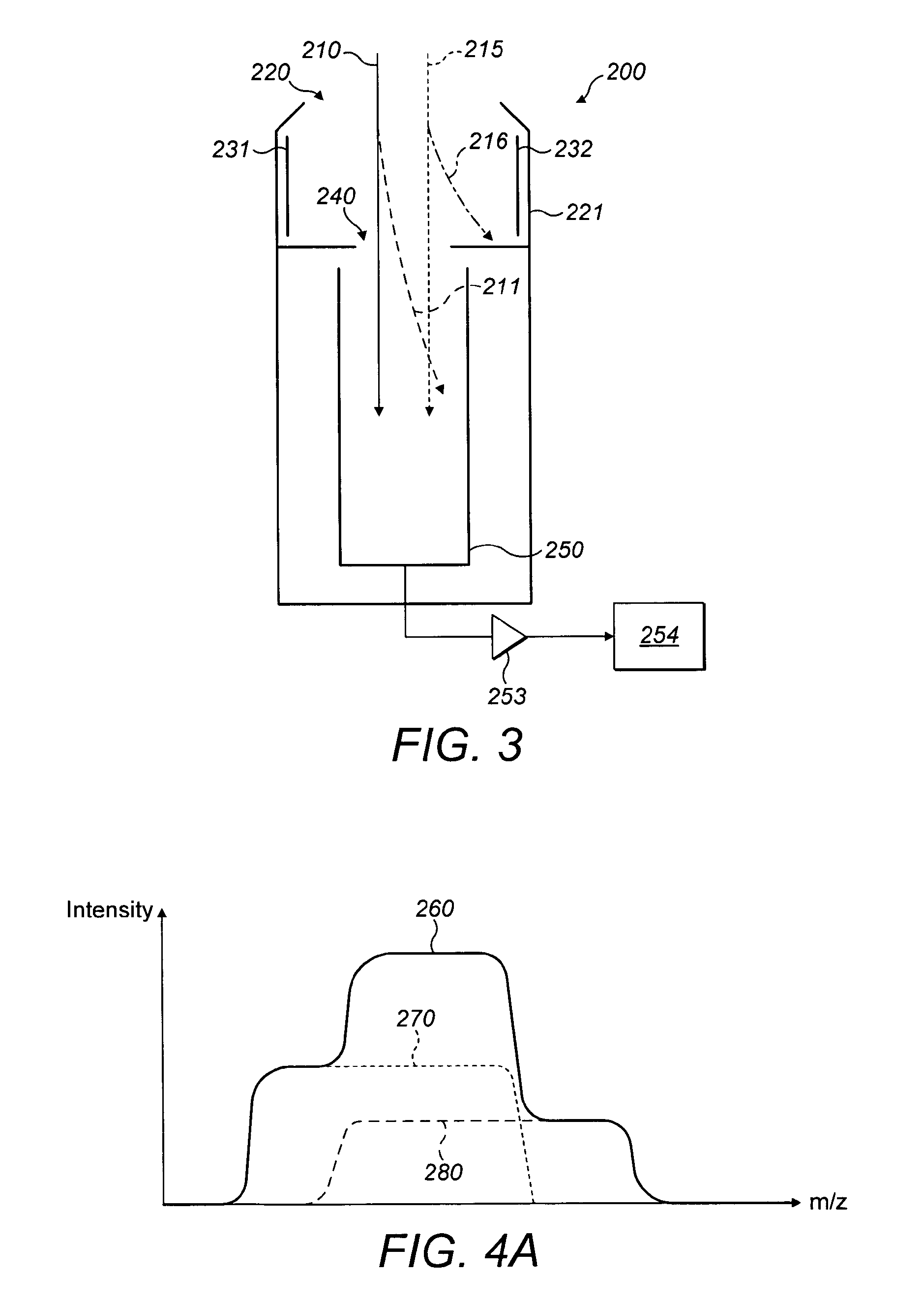
Figure 3
Abstract
Description
TECHNICAL FIELD OF THE INVENTION
[0001] The present invention relates to a mass spectrometer, specifically its ion detection arrangements. The invention also relates to a method of operating a mass spectrometer.BACKGROUND TO THE INVENTION
[0002] Multicollector mass spectrometers are well-known, particularly for distinguishing between isotopes. The detector array may be fixed or movable. Moreover, the distancing between detectors may be fixed within a moveable array. Flexibility of the mass spectrometer for dealing with ions of different types is a consideration in their design.
[0003] WO-97 / 15944 shows a multicollector mass spectrometer comprising a mass analyser having a magnetic sector. A zoom lens is positioned in the path of the ion beam between the output of the mass analyser and the collector array ion detectors. Where the spacing of the separated ions separated by the mass analyser does not precisely match the spacing of the collector array, the zoom lens can provide a small adjust...
Examples
first embodiment
[0070]Referring now to FIG. 2, there is shown the present invention. This is an ion detection arrangement 100, comprising: entrance opening 120; housing 121; first steering plate electrode 131; second steering plate electrode 132; beam defining aperture 140; conversion dynode 151; ion counter dynode 152; amplifier 153; and detection electronics 154.
[0071]In this case, the deflection plate electrodes 131 and 132 are placed in front of the detector beam defining aperture 140 in order to prevent ions in beam 110 from entering the sensitive detection system. The housing 121 provides shielding for the deflection plate electrodes 131 and 132. Although the detector shown is a secondary electron multiplier of discrete dynode type, any detection system which needs to be protected against overloading from high intensity beams may be used with this embodiment. A secondary electron multiplier of continuous dynode type or a sensitive analogue current amplifier could alternatively be used, for in...
second embodiment
[0076]Referring now to FIG. 3, there is shown the present invention. This ion detection arrangement 200 comprises: entrance opening 220; housing 221; first steering plate electrode 231; second steering plate electrode 232; beam defining aperture 240; collector element 250; amplifier 253; and detection electronics 254.
[0077]In this embodiment, a first ion beam 210 and a second ion beam 215 are shown. The first ion beam 210 relates to a first species of ion, and the second ion beam 215 relates to a second species. The two ion beams 210 and 215 are separated in space, but both enter the ion detection arrangement 200 through beam limiting aperture 220, such that there is interference between the ion beams.
[0078]In a first mode of operation, the doublet of both ion beams 210 and 215 is caused to pass through beam defining aperture 240 and a mass spectrum is produced. The resultant mass spectrum 260 is shown is FIG. 4A. The contribution of the first species in ion beam 210 is illustrated ...
third embodiment
[0083]Optionally, deflection plate electrode 232 can be omitted and a positive or negative potential is applied to deflection plate electrode 231. The positioning of the deflection plate electrode 231 can be adjusted accordingly. Referring next to FIG. 5, there is shown the present invention. The ion detector arrangement 300 comprises: an entrance opening 320; housing 321; a first steering plate electrode 331; a second steering plate electrode 332; a first beam defining aperture 340; a second beam defining aperture 345; a first collector element 350; and a second collector element 355.
[0084]The first beam defining aperture 340 is relatively wide in comparison with the second beam defining aperture 345. In this embodiment, it is possible to have a high resolution detector and a low resolution detector installed into the system. The first detector 350 is a low resolution detector and the second detector 355 is of high resolution. By adjusting the potentials applied to the steering pla...