
Motor control apparatus and electric power steering apparatus provided the same
a technology of motor control and electric power steering, which is applied in the direction of electric motor control, electrical steering, transportation and packaging, etc., can solve the problems of motor release switch breaking or destroying, unexpected situation of system abnormality detection time, etc., and achieves the effect of enhancing steering safety and reliability, and cheap constitution
Patent Information
- Authority / Receiving Office
- US · United States
- Patent Type
- Applications(United States)
- Current Assignee / Owner
- Publication Date
- 2018-06-07
- Estimated Expiration
- Not applicable · inactive patent
Smart Images
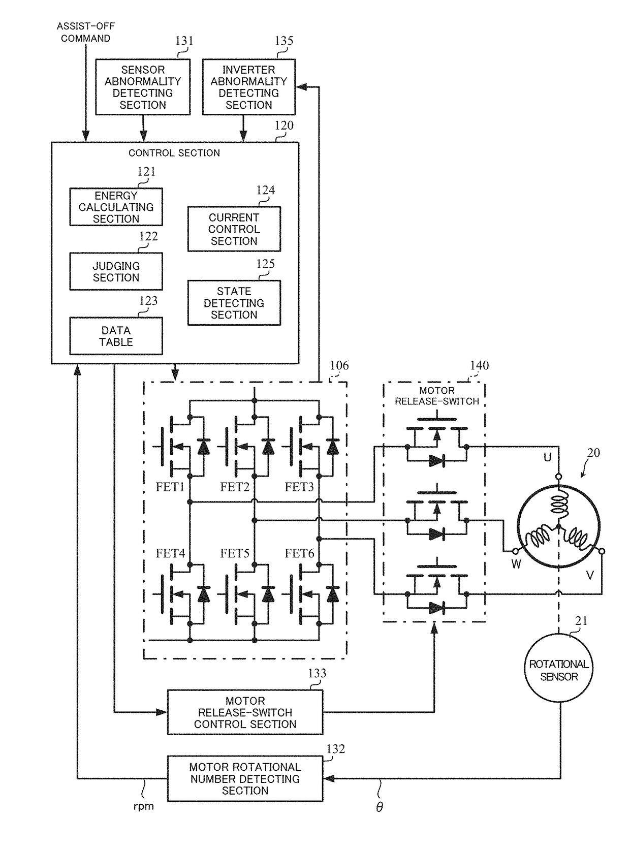
Figure 1 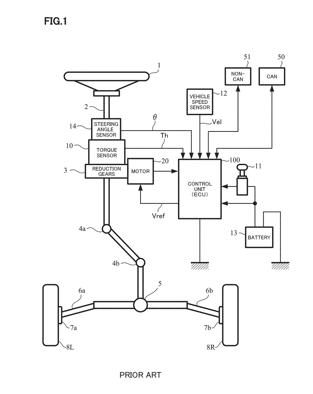
Figure 2 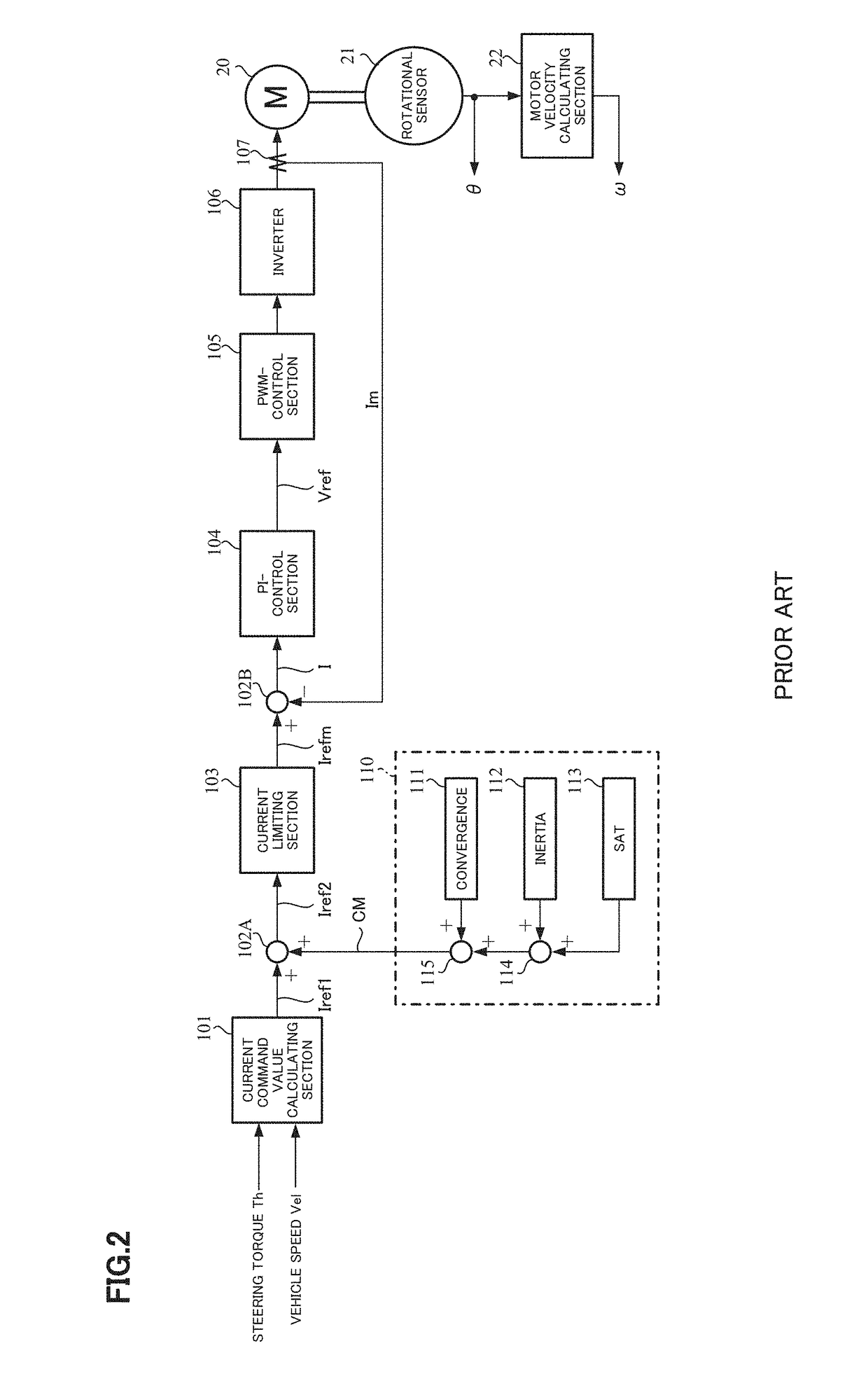
Figure 3
Abstract
Description
TECHNICAL FIELD
[0001] The present invention relates to a motor control apparatus that protects a motor release-switch comprising semiconductor switching elements (e.g. FETs) and being connected to a power supplying section (an inverter) from a regenerative power (obtained with a back-EMF and a regenerative current) energy (power) (and a temperature) caused by a motor rotation when a motor is rotated by an external force, and to an electric power steering apparatus provided the above motor control apparatus.
[0002] The electric power steering apparatus applies an assist force to a steering system of a vehicle by means of the motor due to a current command value calculated based on at least a steering torque and is drive-controlled by the inverter comprising a bridge circuit of the semiconductor switching elements.BACKGROUND ART
[0003] There is an electric power steering apparatus (EPS) as an apparatus provided a motor control apparatus, and the electric power steering apparatus assist-con...
Examples
first embodiment
[0047]In such a constitution, an operation example of the present invention (the first embodiment) will be described with reference to a flow chart of FIG. 6.
[0048]When the control operation is started, first the motor release-switch 140 (140U, 140V, 140W) is ON-switched by the motor release-switch control section 133 through the control section 120 (Step S1). The state detecting section 125 judges whether the abnormality is detected in the sensor abnormality detecting section 131 or the inverter abnormality detecting section 135 or not (Step S2), and ON-switches the control of the inverter 106 by the current control section 124 in the control section 120 when the abnormality is not detected (Step S3). Thereafter, a next control is repeated.
[0049]Further, in a case that the abnormality is detected at the above Step S2, it is judged that the continuation of the assist control is impossible, and the control of the inverter 106 is OFF-switched by the control section 120 (Step S4). The ...
second embodiment
[0055]Next, the second embodiment considered a temperature of the semiconductor switching element or circumference temperature will be described.
[0056]Generally, the area of safety operation (AOS) of operating FET is defined by a relation of a drain current Id and a drain-source voltage Vds as shown in FIG. 7 and a temperature characteristic of the maximum allowable loss Pd as shown in FIG. 8. However, the area of safety operation varies due to operating conditions (an FET-case temperature Tc, an operating frequency f, an ON-width and so on) actually used. Especially, since the maximum allowable loss Pd decreases when the case temperature increases, the temperature information is important in order to obtain an exact the area of safety operation. Since it is possible to estimate the case temperature Tc of the FET if capable of knowing a temperature due to a temperature detecting element on a power substrate, it is possible to calculate the maximum allowable loss Pd corresponding to ...