
Electrolyte storage unit for redox flow battery and vanadium redox flow battery comprising same
a technology of redox flow battery and storage unit, which is applied in the direction of electrolyte stream management, indirect fuel cells, electrochemical generators, etc., can solve the problems of inability to establish stable power supply, serious difficulty in establishing a power supply plan for renewable energy, etc., to improve the self-discharge phenomenon of batteries, improve the capacity and lifespan characteristics of batteries, and facilitate handling and installation
Patent Information
- Authority / Receiving Office
- US · United States
- Patent Type
- Applications(United States)
- Current Assignee / Owner
- Publication Date
- 2019-04-04
Smart Images
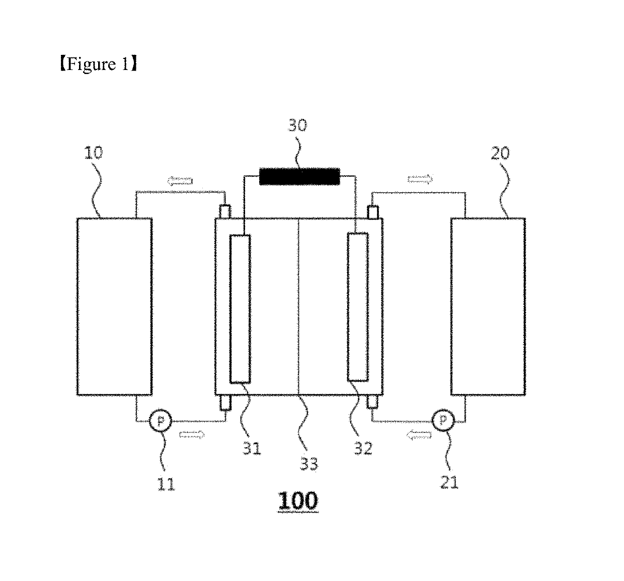
Figure 1 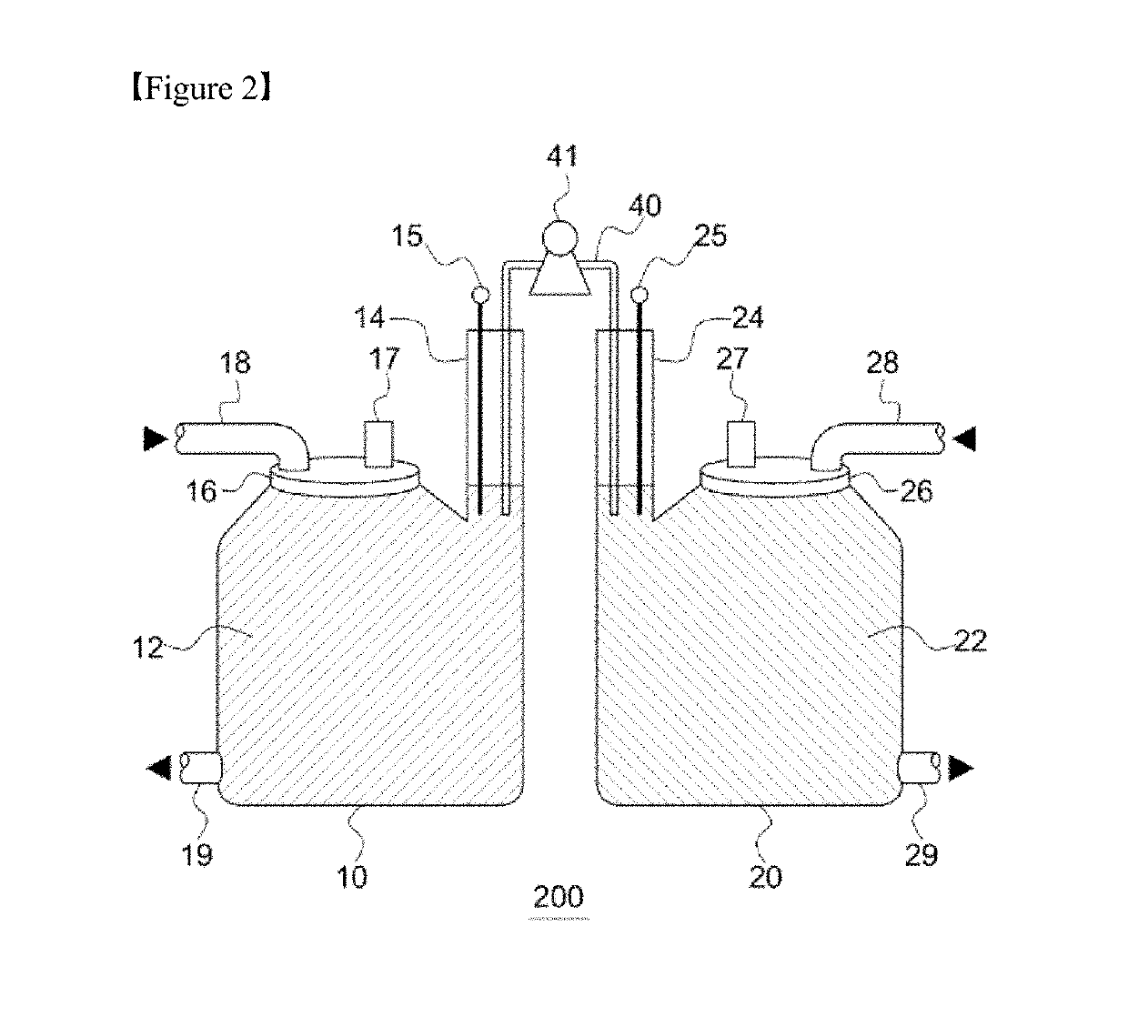
Figure 2 
Figure 3
Abstract
Description
TECHNICAL FIELD
[0001] This application claims priority to and the benefit of Korean Patent Application No. 10-2016-0132669, filed Oct. 13, 2016, the disclosure of which is incorporated herein by reference in its entirety.
[0002] The present invention relates to an electrolyte storage unit applicable to redox flow batteries and a vanadium redox flow battery including the same.BACKGROUND ART
[0003] With the increasing global awareness of problems regarding environmental pollution and global warming caused due to the dramatic increase in demand for energy and the use of fossil fuels, renewable energy has attracted attention as a future energy source. However, renewable energy has a serious difficulty in establishing a power supply plan because stable power supplies are impossible due to a large power variation according to a change in climate environment. As an alternative to solve the above problems, the importance of an energy storage system (ESS) configured to store electric power which ...
Examples
experimental example 1
Performance
[0084]The battery manufactured in Preparative Example 1 was used in Example 1, and battery performance of the battery was evaluated. In this case, a redox flow battery having the same battery configuration as in Preparative Example 1, in which no electrolyte was transferred during battery driving, was used in Comparative Example. The battery driving conditions are as follows.
[0085]Electrolyte supply rate: 2 mL / min / cm2
[0086]Charge / discharge current density: 100 mA / cm2, constant current
[0087]Charge / discharge voltage: 0.8 to 1.7 V
[0088]Electrolyte supply rate by pump in transfer pipe: 0.3 mL / min / cm2
[0089]The experimental results are shown in FIGS. 5 and 6. FIG. 5 is a graph plotted for discharge capacities of the batteries of Example 1 and Comparative Example 1, and FIG. 6 is a graph plotted for current efficiency (CE), voltage efficiency (VE), and energy efficiency (EE).
[0090]Referring to FIG. 5, it can be seen that an effect of increase in capacity was immediately expres...