
Trench mosfets having dummy cells for avalanche capability improvement
Patent Information
- Authority / Receiving Office
- US · United States
- Current Assignee / Owner
- Publication Date
- 2021-04-08
Smart Images
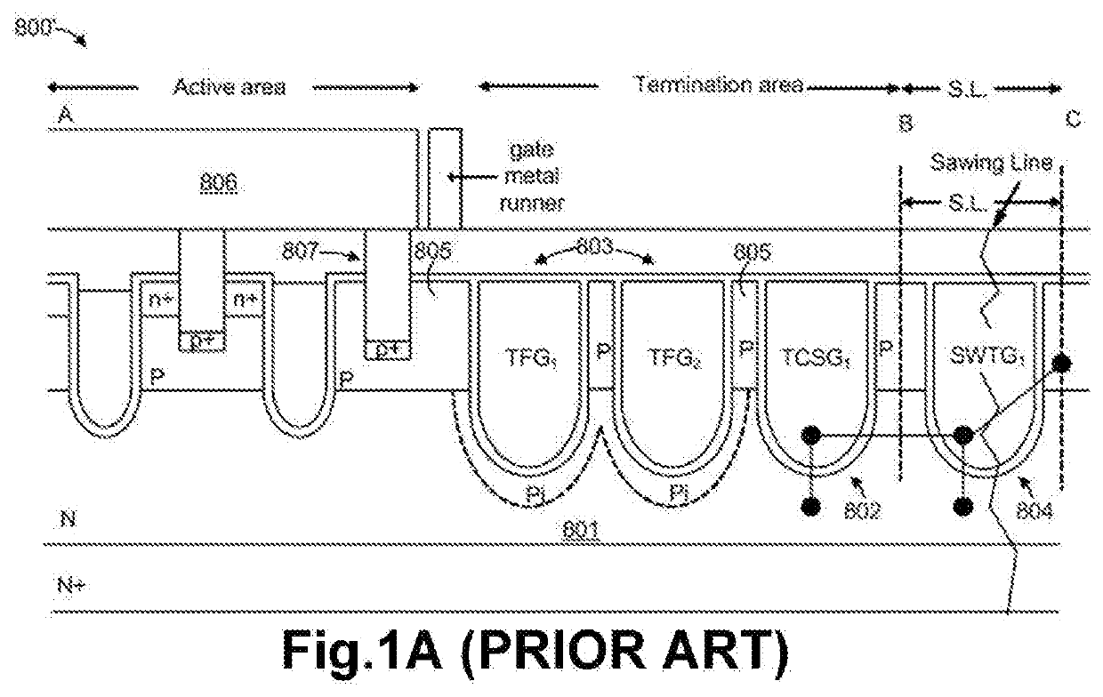
Figure 1 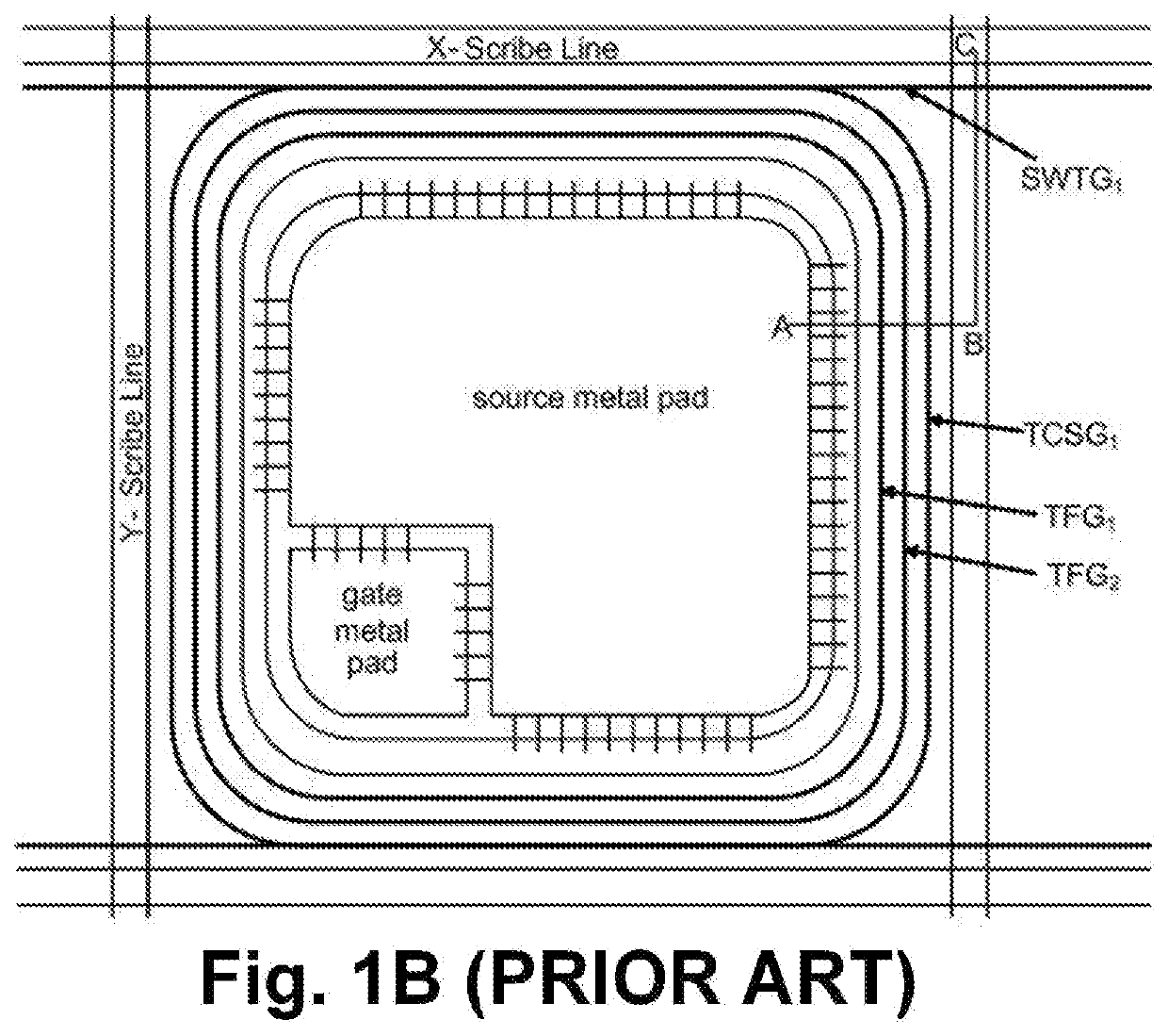
Figure 2 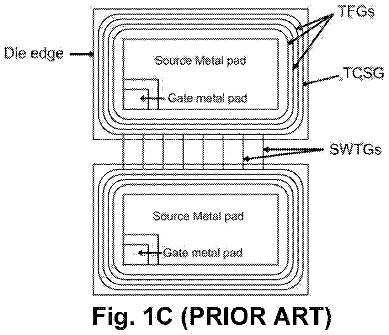
Figure 3
Abstract
Description
FIELD OF THE INVENTION
[0001] This invention relates generally to the cell structure, layout and device configuration of power semiconductor devices. More particularly, this invention relates to a novel and improved cell structure, layout and device configuration for fabricating trench MOSFET (Metal Oxide Semiconductor Field Effect Transistor) having dummy cells without having source regions for avalanche capability improvement.BACKGROUND OF THE INVENTION
[0002] In U.S. Pat. Nos. 8,519,477 and 8,487,372, trench MOSFETs were disclosed having body and source regions between trench gates in active area (as shown in FIG. 1A), multiple floating trench gates (FTG) and channel stop trench gates (CSTG) surrounding the active area in termination area and sawing trench gates (SWTG) across scribe line area (as shown in FIG. 1B and FIG. 1C). The prior arts structures in termination area are used to avoid channeling between drain and source.
[0003] FIG. 1E is a top view of the trench MOSFETs of the pr...
Examples
Embodiment Construction
[0026]In the following Detailed Description, reference is made to the accompanying drawings, which forms a part thereof, and in which is shown by way of illustration specific embodiments in which the invention may be practiced. In this regard, directional terminology, such as “top”, “bottom”, “front”, “back”, etc., is used with reference to the orientation of the Figure(s) being described. Because components of embodiments can be positioned in a number of different orientations, the directional terminology is used for purpose of illustration and is in no way limiting. It is to be understood that other embodiments may be utilized and structural or logical changes may be made without departing from the scope of the present invention. The following detailed description, therefore, is not to be taken in a limiting sense, and the scope of the present invention is defined by the appended claims. It is to be understood that the features of the various exemplary embodiments described herein...