
Relief object image generator
Patent Information
- Authority / Receiving Office
- US · United States
- Current Assignee / Owner
- Publication Date
- 2005-02-15
- Estimated Expiration
- Not applicable · inactive patent
Smart Images
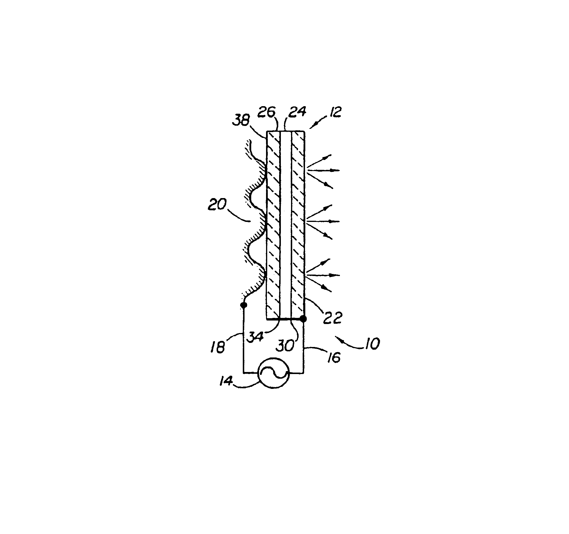
Figure 1 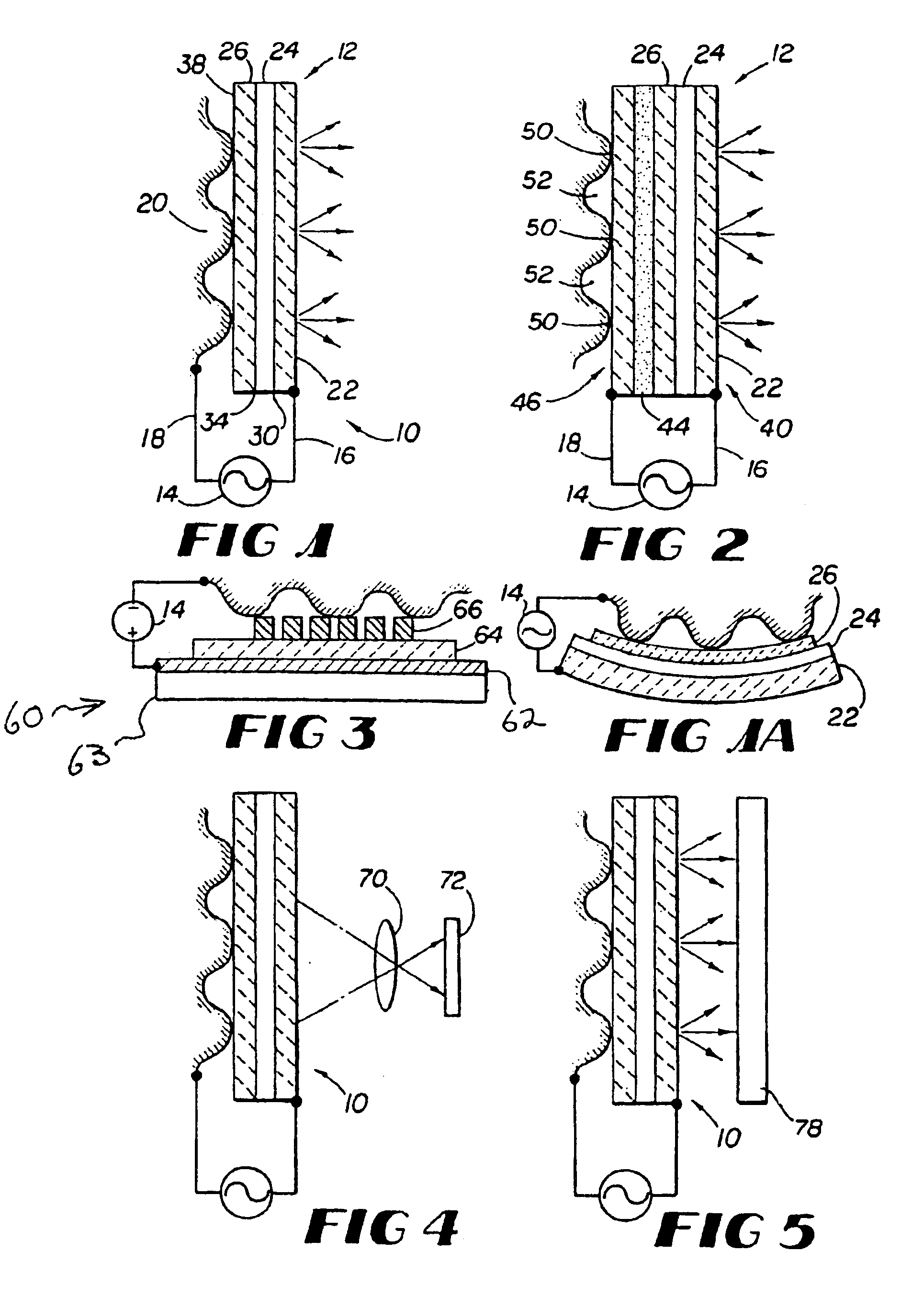
Figure 2
Abstract
Description
FIELD OF THE INVENTIONThis invention relates to image generation, and more particularly, to image generation of relief objects.BACKGROUND OF THE INVENTIONSystems for generating images of relief objects are known. Relief objects are objects having a surface with features typically formed by ridges and valleys. A common relief object imaged by known technology is a fingerprint. These known systems include a platen to which a relief object is pressed to expose the ridges and valleys of the relief object to imaging equipment. The platen is illuminated by a light source. In many relief object imaging systems, the light from the light source is passed through a collimator before it illuminates the platen. The light is typically coupled through a right-angle prism to the platen at or near an angle corresponding to Total Internal Reflection (TIR). TIR refers to the frustration or absorption of light at the ridges of the relief object and its reflection back through the platen at the valleys...
Examples
Embodiment Construction
A system for imaging relief objects in accordance with the principles of the present invention is shown in FIG. 1. Image generator 10 includes a single electrode electroluminescent device 12 and an electrical current source 14. The electrical current source has a lead 16 which is coupled to electroluminescent device 12, and a second lead 18 for coupling current to a relief object when it is placed against or proximate to electroluminescent device 12. In response to the current coupled from the relief object to electroluminescent device 12, different areas of electroluminescent device 12 generate light at intensities which correspond to the amount of current coupled to an area of electroluminescent device 12. Electroluminescent device 12 may be constructed from known inorganic electroluminescent devices that include two planar electrodes which are mounted at opposite ends of the electroluminescent device so they cover the length and width of the device and are aligned with one anothe...