
Double layer forming fabric with high center plane resistance
Patent Information
- Authority / Receiving Office
- US · United States
- Current Assignee / Owner
- Publication Date
- 2008-09-23
Smart Images
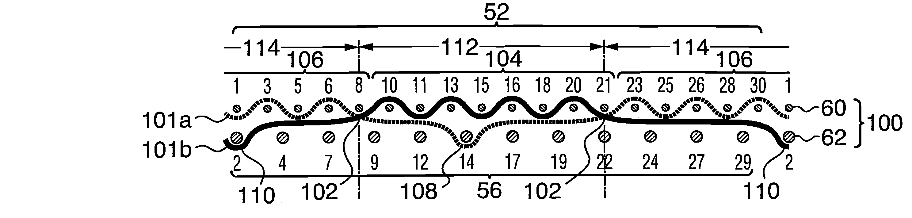
Figure 1 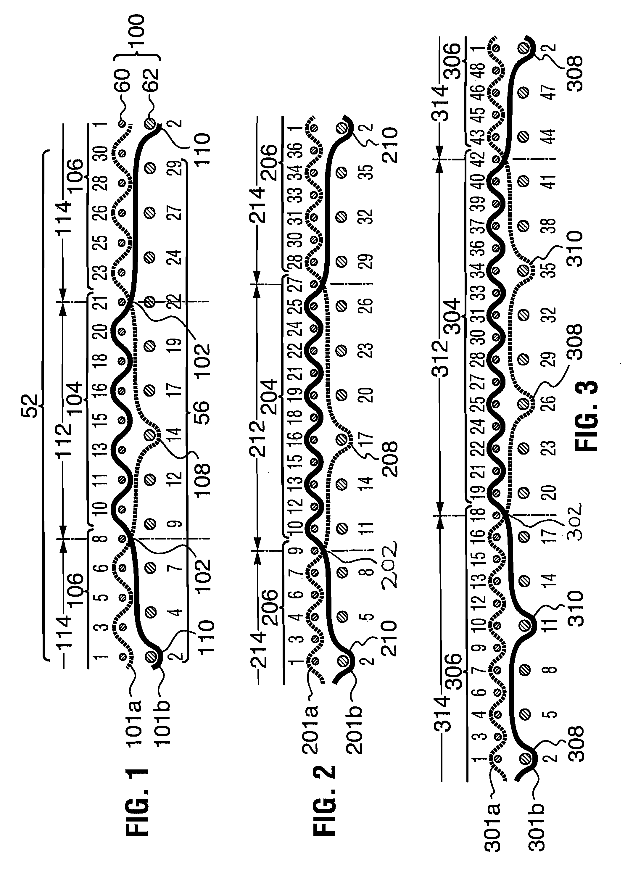
Figure 2 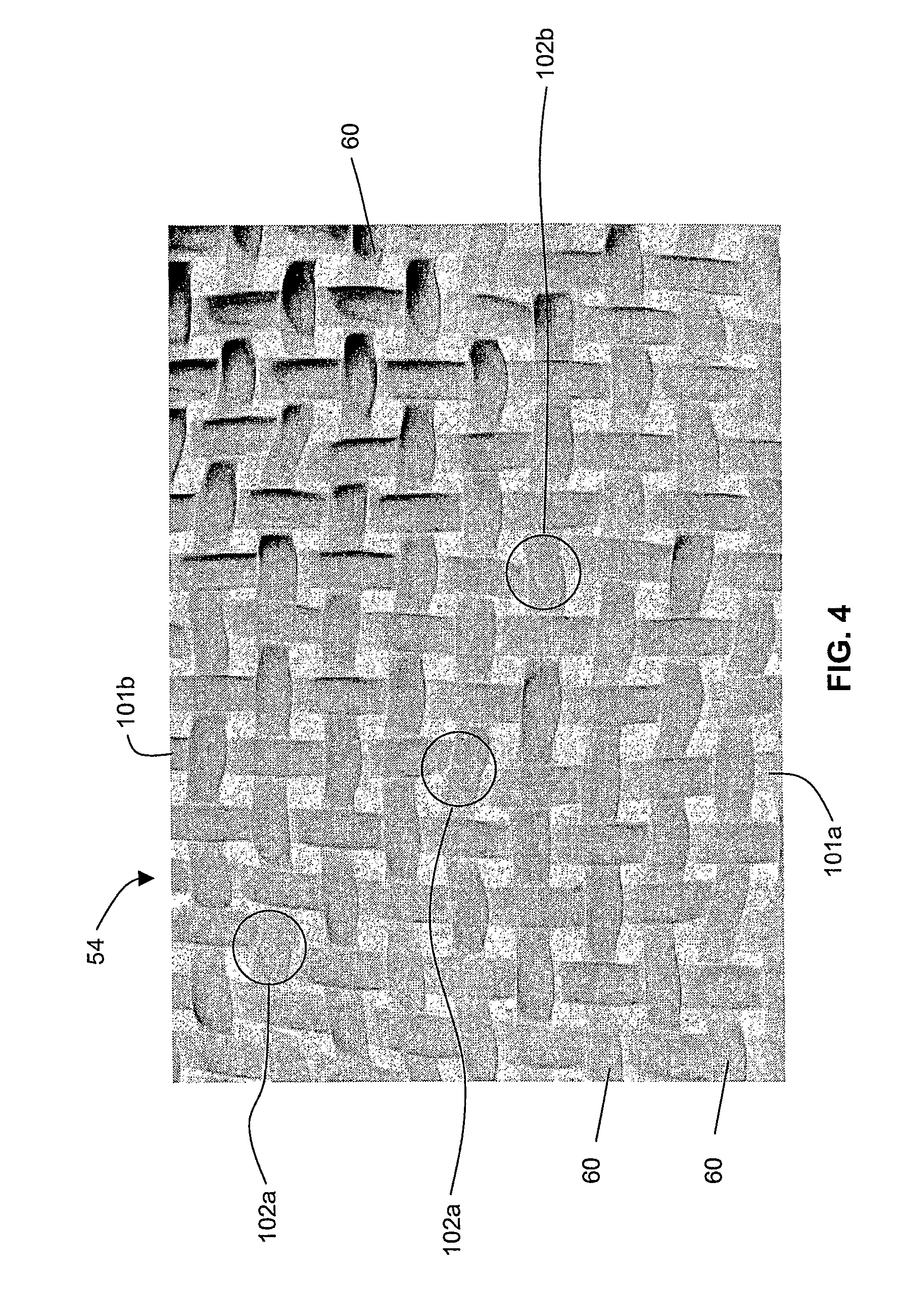
Figure 3
Abstract
Description
FIELD OF THE INVENTION
[0001] The present invention relates to forming fabrics for use in papermaking machines. It is particularly concerned with double layer forming fabrics which are structured to provide a low drainage area in a notional centre plane between the paper and machine side layers so as to resist and retard initial impingement drainage through the fabrics.BACKGROUND OF THE INVENTION
[0002] As used herein, the term “double layer forming fabric” refers to forming fabrics comprising two sets of yarns oriented in a first direction, one set located on the paper side and the other set located on the machine side of the fabric, and which are bound together by a single set of binder yarns oriented in a transverse direction and woven as pairs. The weave patterns of each of the paper and machine side surfaces, as determined by the overall fabric weave pattern, are either substantially the same or different. Further, as used herein, the term “transverse” refers to either the machine ...
Examples
first embodiment
[0083]Referring to FIGS. 1, 4 and 10, the invention is shown. The fabric 100 has a paper side layer 52, having a paper side surface 54, on which the incipient paper web (not shown) is carried, and is woven to a plain weave pattern with paper side layer weft yarns 60 and pairs of warp yarns 101a and 101b. The machine side layer 56 is woven to a different pattern, comprising an N×2N weave, in which N quantifies the warp yarns 101a, 101b, and 2N quantifies the weft yarns 62 in one repeat of the machine side layer weave pattern. In the fabrics of the invention, N is an integer greater than 3. This N×2N pattern is described and claimed in U.S. Pat. No. 5,544,678.
[0084]In FIG. 1, the paper side layer weft yarns 60 and the machine side layer weft yarns 62 are individually identified by the appropriate numerals in sequence from 1 to 30.
[0085]FIGS. 1 and 10 show the path of a pair of typical warp yarns 101a and 101b in one repeat of the fabric weave pattern. It can be seen that in a first se...
second embodiment
[0092]Referring now to FIG. 2, the paths of a pair of typical warp yarns 201a, 201b of a second embodiment are shown, in one repeat of the weave pattern. In FIG. 2, the paper side layer weft yarns 60 and the machine side layer weft yarns 62 are individually identified by the appropriate numerals in sequence from 1 to 36.
[0093]As in the embodiment of FIG. 1, the two warp yarns 201a, 201b together form a single combined warp path in the paper side surface 54 (see FIG. 4) of the paper side layer 52, while being somewhat laterally displaced at and between the exchange points 202. Similarly, the warp yarns 201a, 201b have long internal floats with a float length of at least 4 between each interlace location 208, 210 and the immediately preceding and immediately subsequent exchange point 202. In this weave pattern, in a first segment 212, warp yarn 201b interweaves at interweave location 204 with twelve paper side layer weft yarns 10, 12, 13, 15, 16, 18, 19, 21, 22, 24, 25 and 27, and in ...
third embodiment
[0095]Referring now to FIG. 3, the paths of a pair of warp yarns 301a, 301b of a third embodiment are shown, in one repeat of the weave pattern. In FIG. 3, the paper side layer weft yarns 60 and the machine side layer weft yarns 62 are individually identified by the appropriate numerals in sequence from 1 to 48.
[0096]As in the embodiments of FIGS. 1 and 2, the two warp yarns 301a, 301b together form a single combined warp path in the paper side surface 54 (see FIG. 4) of the paper side layer 52, while being somewhat laterally displaced at and between the exchange points 302. Similarly, the warp yarns 301a, 301b have long internal floats with a float length of at least 4 between each first interlace location 308 and the immediately preceding exchange point 302; and similarly between each second interlace location 310 and each subsequent exchange point 302. Further, between the two interlace locations 308, 310 for each of warp yarns 301a, 301b, there is a further long internal float w...