
Coil antenna and non-contact information medium
a non-contact information medium and coil antenna technology, applied in the direction of loop antennas with ferromagnetic cores, loop antennas with screened antennas, instruments, etc., can solve the problems of reducing the effect of mutual interaction with the reader/writer, reducing the resonant frequency of the non-contact information medium, and failing to perform communication, etc., to achieve a small mutual inductance, reduce the ratio of self-inductance to mutual inductance, and reduce the ratio of mutual inductance ratio ratio ratio ratio ratio ratio ratio ratio ratio ratio ratio ratio ratio ratio ratio ratio ratio ratio ratio ratio ratio ratio ratio ratio ratio ratio ratio ratio ratio ratio ratio ratio ratio ratio ratio ratio ratio ratio ratio ratio ratio ratio ratio ratio ratio ratio ratio ratio ratio ratio ratio ratio ratio ratio ratio ratio ratio ratio ratio ratio ratio ratio ratio ratio ratio ratio ratio ratio ratio ratio ratio ratio ratio ratio ratio ratio ratio ratio ratio
Patent Information
- Authority / Receiving Office
- US · United States
- Patent Type
- Patents(United States)
- Current Assignee / Owner
- Publication Date
- 2012-10-30
Smart Images
Figure 1 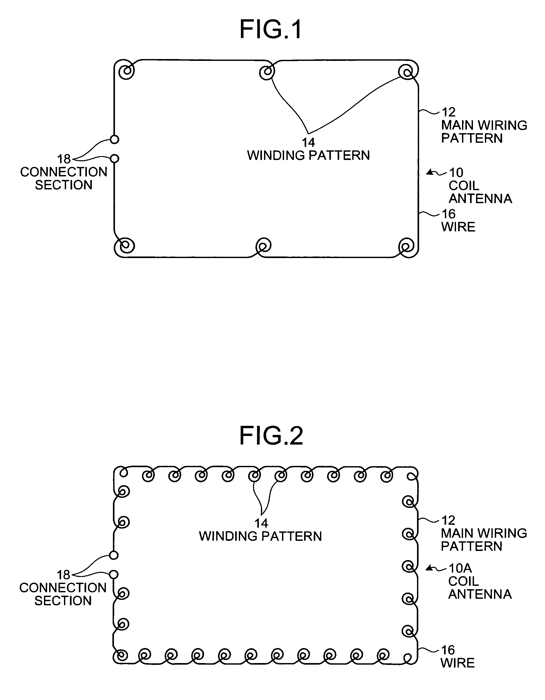
Figure 2 
Figure 3
Abstract
Description
TECHNICAL FIELD
[0001] The present invention relates to a coil antenna, and a non-contact information medium using the coil antenna.BACKGROUND ART
[0002] Coil antennas used to provide and receive information using electromagnetic induction is constituted by a resonant circuit, and a resonant frequency is generally adjusted (tuned) to efficiently provide and receive information. Important parameters for determining a resonant frequency of a resonant circuit include self-inductance and capacitance of the resonant circuit. The resonant frequency is generally adjusted by changing values of these self-inductance and capacitance.
[0003] When a plurality of electrical circuits with self-inductance is placed close to each other, mutual inductance occurs. This mutual inductance is also an important parameter for efficiently providing and receiving information. In general, the mutual inductance is designed to have a value as large as possible in an assumed use environment, aiming to achieve strong ...
Examples
first embodiment
[0090]FIG. 1 is a schematic view of a coil antenna 10 according to a first embodiment. As shown in FIG. 1, the coil antenna 10 according to the first embodiment includes a main wiring pattern 12 and a plurality of winding patterns 14, all formed with the same wire 16. The main wiring pattern 12 is arranged in a rectangular loop shape of a predetermined size, and has connection sections 18 at both ends thereof respectively that are electrically connected to, for example, a capacitor (not shown) forming a resonant circuit. The loop shape of the main wiring pattern 12 is not limited to a rectangular shape and may be a suitable shape, for example, a round shape, depending on an object (the same applies to the following embodiments). For example, on the same plane on which the main wiring pattern 12 is arranged, the winding patterns 14 are formed to have spiral shapes distributed to six locations in the inner periphery of the main wiring pattern 12. The spiral wound shapes of the winding...
second embodiment
[0098]FIG. 4 is a schematic perspective view of a coil antenna 20 according to a second embodiment. As shown in FIG. 4, the coil antenna 20 according to the second embodiment includes a main wiring pattern 22 and a winding pattern 24, both formed with the same wire 26. The main wiring pattern 22 is arranged in a rectangular loop shape of a predetermined size, and has connection sections 28 at both ends thereof respectively that are electrically connected to, for example, a capacitor (not shown) forming a resonant circuit. The winding pattern 24 is formed, for example, in a spiral shape on a plane Pb orthogonal to a plane Pa on which the main wiring pattern 22 is arranged. The winding pattern 24 is formed to traverse a center portion of the main wiring pattern 22, and is thereby distributed to the entire main wiring pattern 22. The spiral wound shape of the winding pattern 24 has a length traversing the main wiring pattern 22 but is formed to be flat on the plane Pb, thus being small...
third embodiment
[0102]FIG. 5 is a schematic perspective view of a coil antenna 30 according to a third embodiment. As shown in FIG. 5, the coil antenna 30 according to the third embodiment includes a main wiring pattern 32 and a winding pattern 34, both formed with the same wire 36. The main wiring pattern 32 is arranged in a rectangular loop shape of a predetermined size, and has connection sections 38 at both ends thereof respectively that are electrically connected to, for example, a capacitor (not shown) forming a resonant circuit. The winding pattern 34 is formed, for example, in a spiral shape and distributed continuously along one side of the main wiring pattern 32. The winding pattern 34 is formed, for example, in a flat spiral shape over planes Pc orthogonal to one side of the plane Pa on which the main wiring pattern 32 is arranged. The spiral wound shape of the winding pattern 34 is formed to be small enough compared with the size of the main wiring pattern 32.
[0103]The self-inductance o...