
Diverting pulley arrangement and elevator
a technology of diverting pulleys and pulleys, which is applied in the direction of elevators, hoisting equipment, transportation and packaging, etc., can solve the problems of not eliminating the support of diverting pulleys, and achieve the effect of reducing the dependence on the direction of rotation
Patent Information
- Authority / Receiving Office
- US · United States
- Patent Type
- Patents(United States)
- Current Assignee / Owner
- Publication Date
- 2015-04-21
Smart Images
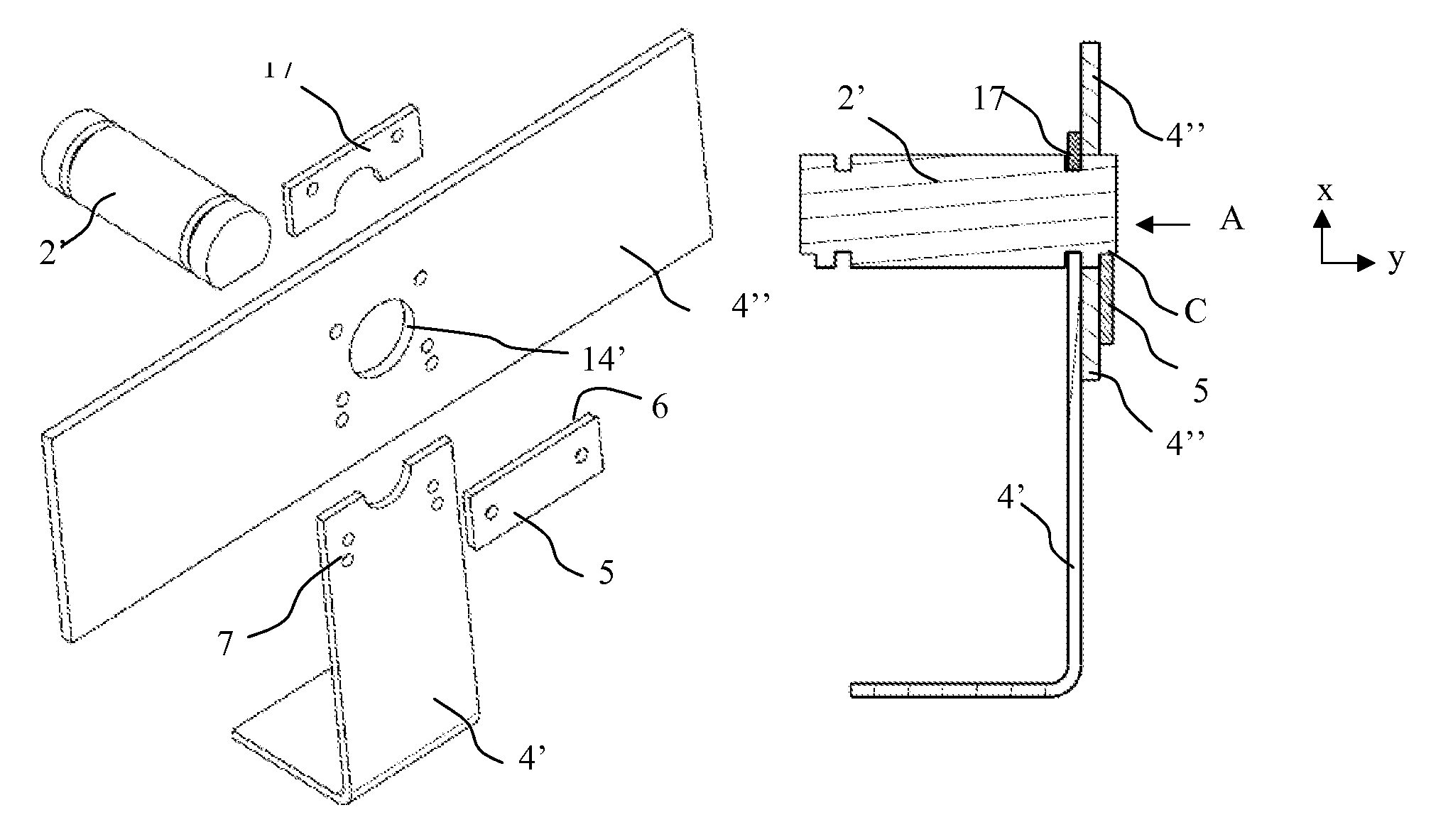
Figure 1 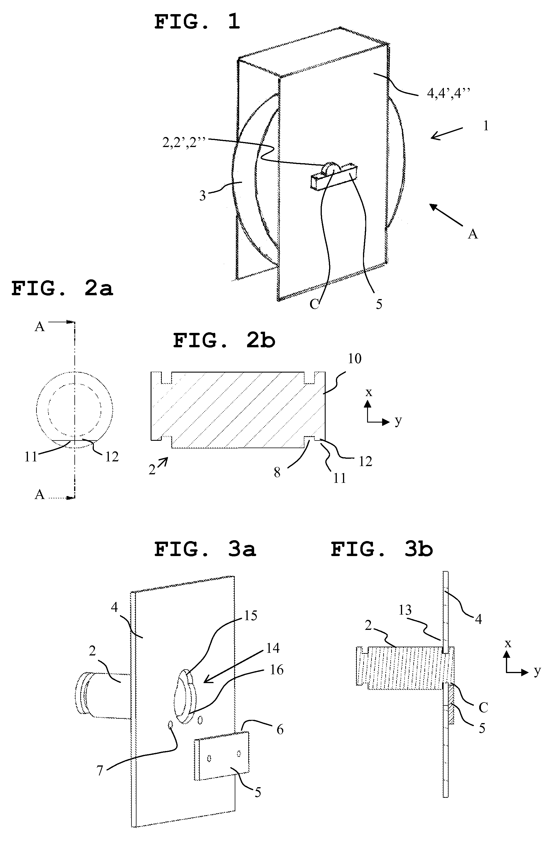
Figure 2 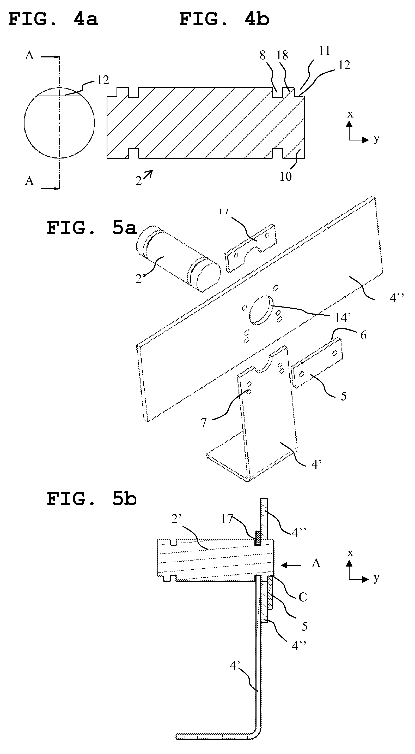
Figure 3
Abstract
Description
FIELD OF THE INVENTION
[0001] The object of the invention is a diverting pulley arrangement preambleBACKGROUND OF THE INVENTION
[0002] In prior-art diverting pulleys the axle of the diverting pulley is locked into position with a locking plate that extends into a groove made in the axle. The groove is milled into the axle from the transverse direction, in which case the groove comprises a detent surface as viewed in the transverse direction of the axle, against which the locking plate is placed to lock the axle in position so that it does not rotate and does not move in the axial direction. A problem in these prior-art solutions is that when the locking plate breaks and allows the axle to rotate, movability of the axle is also enabled in the axial direction. Another problem in these prior-art solutions is that since the groove is milled in the solutions at a distance from the end of the axle, the detent surface that is against the locking plate has remained hidden behind the end of the ...
Examples
Embodiment Construction
[0047]FIG. 1 presents in principle an assembly drawing of one diverting pulley arrangement 1 according to the invention, which comprises an axle 2,2′,2″, at least one diverting pulley 3 that rotates preferably around the axle while supported on the axle, a faceplate structure 4,4′,4″ on the side of the diverting pulley, which faceplate structure preferably comprises at least one faceplate, in relation to which and supported by which faceplate structure the diverting pulley 3 is arranged to rotate supported on the axle 2,2′,2″ on the first side of the faceplate structure. The axle 2,2′,2″ is locked so that it does not rotate in relation to the faceplate structure by the aid of a locking element 5, which locking element 5 is on the second side of the faceplate structure 4,4′,4″, which second side is on the opposite side to the first side and supported so that it does not move in relation to the faceplate structure 4,4′,4″. The locking element 5 is placed against the detent surface 6 o...