Heat exchanger in particular for exhaust coolers on internal combustion engines

A heat exchanger and inner tube technology, applied in the field of heat exchangers, can solve problems such as flow leakage and achieve the effect of thermal expansion

Inactive Publication Date: 2009-09-23
贝洱公司
View PDF5 Cites 0 Cited by
  • Summary
  • Abstract
  • Description
  • Claims
  • Application Information

AI Technical Summary

Problems solved by technology

[0005] A frequent problem in such partitions is flow leakage, which occurs in the area of ​​the partition and on the passage from the partition to the heat exchange pipes or bypass pipes

Method used


Image

  • Heat exchanger in particular for exhaust coolers on internal combustion engines
  • Heat exchanger in particular for exhaust coolers on internal combustion engines
  • Heat exchanger in particular for exhaust coolers on internal combustion engines

Examples


Embodiment Construction

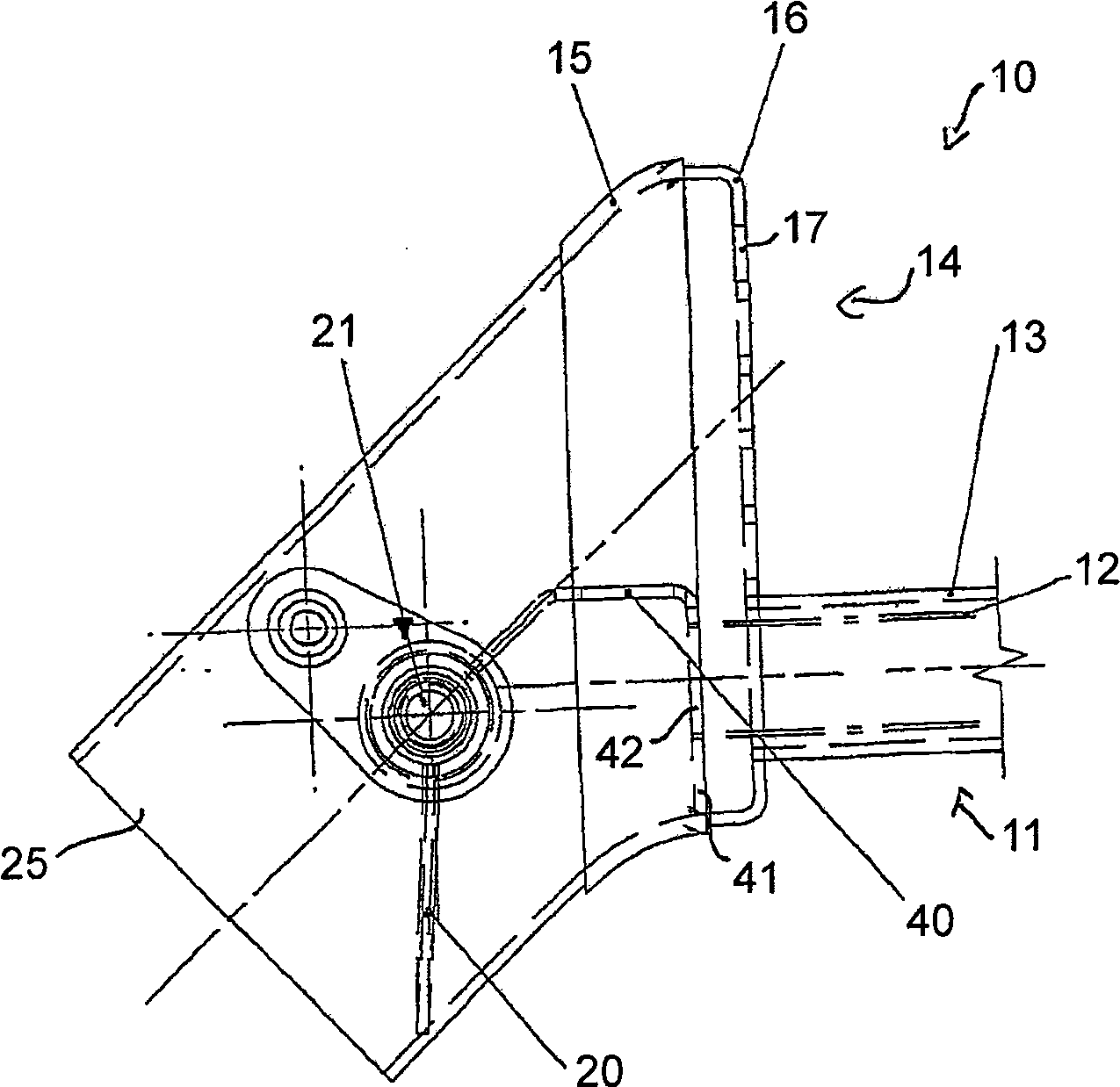
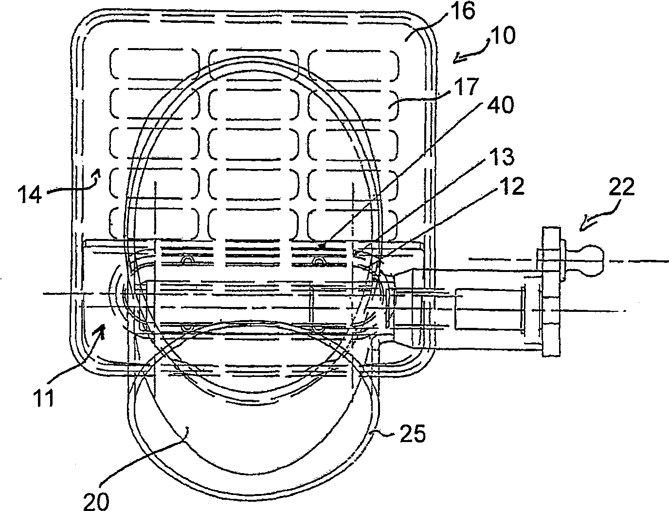
[0023] figure 1 and 2 A longitudinal and transverse section through the heat exchanger 10 is shown in the flow guide of the carrier medium in the inflow region. The heat exchanger 10 is designed as a double pipe, one of the two pipes forming the bypass pipe 11 and the other pipe forming the heat exchange pipe 14 . The heat exchange lines 14 are designed to exchange energy between the carrier medium and the heat exchange medium formed in the region of the heat exchange lines 14 (exchanging energy to the carrier medium) and thus to heat or cool the carrier medium. In the exemplary embodiment shown, the heat exchanger is used for an exhaust gas cooler of an internal combustion engine, in which the carrier medium is formed by the exhaust gas flow and correspondingly supplied with cooling water as heat exchange medium. The heat of the carrier medium - exhaust gas is transferred to the heat exchange medium - water and reduces the temperature of the exhaust gas stream.

[0024] Th...


PUM


Abstract

The invention relates to a heat exchanger (10), in particular a heat exchanger for an exhaust gas cooler of an internal combustion engine. The object of the present invention is to achieve a separation of the carrier medium into two partial flows with as little flow leakage as possible by means of a suitable structure of the partition ( 40 ). The heat exchanger ( 10 ) can be used as an exhaust gas cooler for an internal combustion engine, the heat exchanger having a heat exchange line ( 14 ) and a bypass line ( 11 ), wherein, in the flow line ( 25 ), in the heat exchanger A switching valve (20) is provided upstream, which separates the carrier medium flowing into the heat exchange conduit and the bypass conduit. In order to maintain the separation between the split flow through the bypass duct (11) and the split flow through the heat exchange duct (14), a partition (40) is provided, which according to the invention extends from the switching valve (20) all the way to the beginning of the bypass pipe (11).

Description

technical field [0001] The invention relates to a heat exchanger, in particular for an exhaust gas cooler of an internal combustion engine. Background technique [0002] Heat exchangers for use in a variety of applications are well known. Furthermore, the arrangement of so-called bypass lines is known, which guides the carrier medium flowing through the heat exchanger sideways on the heat exchanger body. In addition, when the carrier medium flows through the heat exchanger, when the carrier medium flows in the heat exchange area, transfers energy to the heat exchange medium or transfers energy from the heat exchange medium to the carrier medium, the heat exchange medium does not generate substantial energy with the carrier medium exchange. [0003] In order to regulate or control the temperature generated by the carrier medium downstream of the heat exchanger, it is known to provide a switching valve in the flow line leading to the heat exchanger upstream of the heat excha...

Claims


Application Information

Patent Timeline
Patent Type & Authority Patents(China)
IPC IPC(8): F01N3/04
CPCY02T10/121Y02T10/16
Inventor 克劳斯·贝克赫维·帕朗雄马丁·申德勒
Owner 贝洱公司
Why Eureka
Try Eureka