Intelligent entrance angle speed-limiting igniter

A speed limit point, igniter technology, applied in the direction of electrical automatic control, automatic control, automatic control, etc., can solve the problem that the speed limit igniter cannot be eliminated, and achieve stable and reliable speed limit, smooth operation, and no sense of rush Effect

Inactive Publication Date: 2010-02-17
樊荣群
View PDF3 Cites 0 Cited by
  • Summary
  • Abstract
  • Description
  • Claims
  • Application Information

AI Technical Summary

Problems solved by technology

At present, there is no speed-limiting igniter that can eliminate the above defects

Method used


Image

  • Intelligent entrance angle speed-limiting igniter
  • Intelligent entrance angle speed-limiting igniter
  • Intelligent entrance angle speed-limiting igniter

Examples


Embodiment Construction

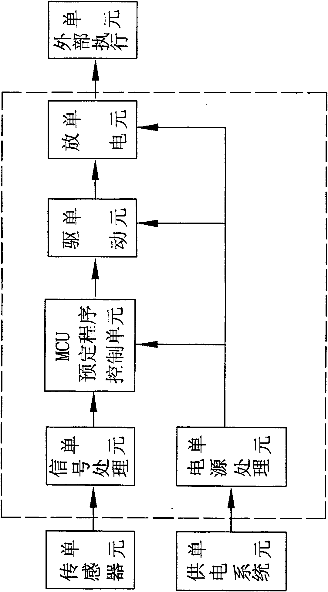
[0022] refer to figure 1 , the intelligent advance angle speed limit igniter of the present invention comprises the sensor unit that is used to detect the engine speed; The signal processing unit that accepts the output signal of the sensor unit; The MCU predetermined program control unit is used to accept the signal of the signal processing unit, Output control signal; the discharge unit used to make the secondary pole of the ignition coil of the motorcycle engine generate a momentary high voltage to realize the ignition function; the drive unit used to receive the signal sent by the MCU predetermined program control unit to make the discharge unit work; And a power processing unit that supplies power to the MCU predetermined program control unit, drive unit and discharge unit.

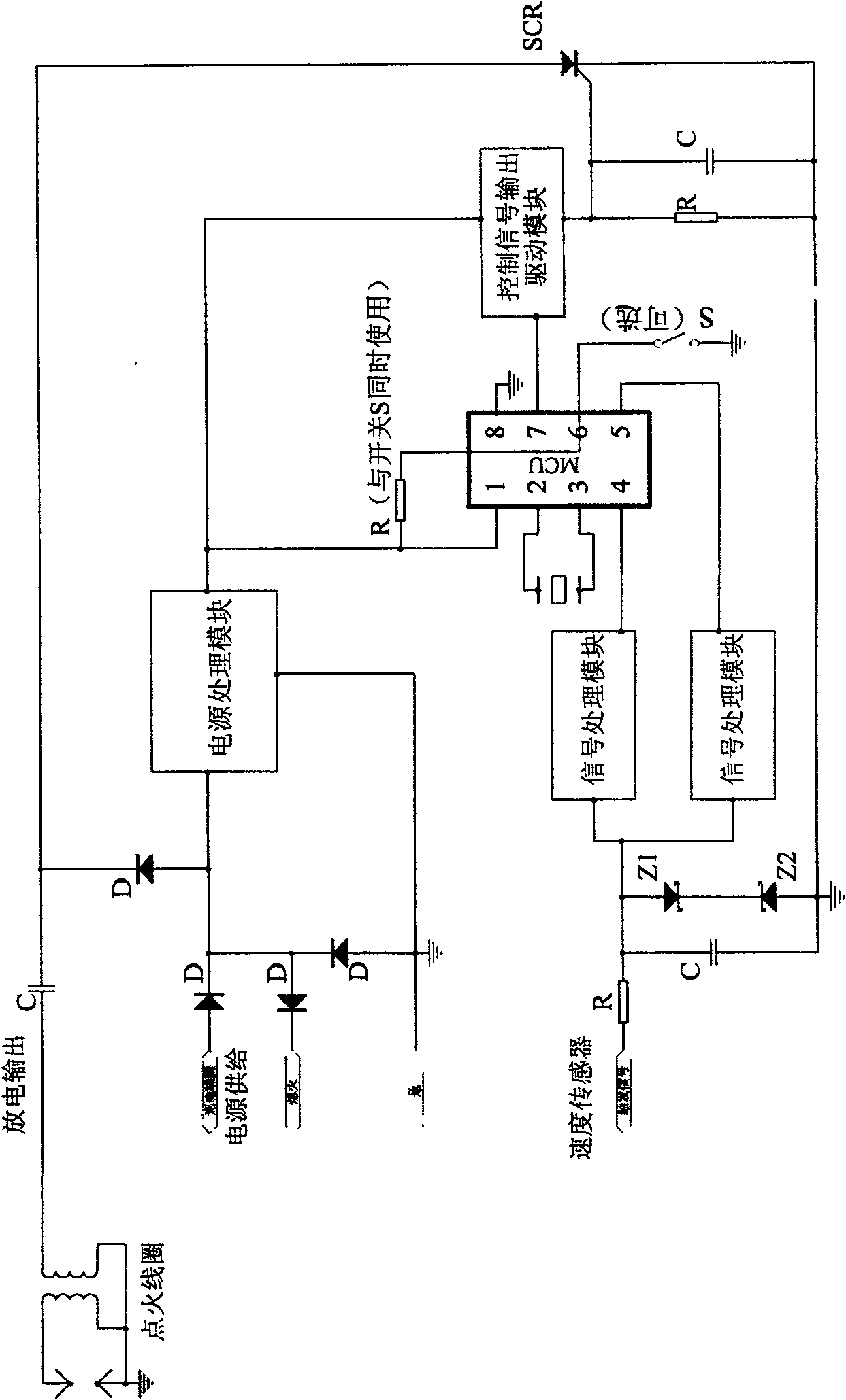
[0023] refer to figure 2 , the specific circuit of the intelligent timing speed limit igniter is as follows, the speed sensor of the igniter is connected to the motorcycle magneto, and the output e...


PUM


Abstract

This invention discloses one intelligent inlet angle limit lighter, wherein, the current motor limit is by mechanic or lighter for flameout at certain speed of generator, but that method can result insuper hot temperature, costly oil and large noise with apparent impacting effect. This invention lighter adopts outlet angle lighting means or proportion lighting type to limit motor rotation to trace motor speed change to adjust to realize motor needed limit speed.

Description

technical field [0001] The invention relates to an igniter for a motorcycle, in particular to an igniter for speed-limiting the speed of an engine by using a receding-angle ignition mode or a proportional-interval ignition mode. Background technique [0002] Existing motorcycle speed limit mainly relies on mechanical speed limit or the mode that uses igniter to promptly go out when engine reaches certain rotating speed. However, the method of mechanical speed limit is easy to cause excessive engine speed and overheating, high fuel consumption and high noise. Using the method of igniter to turn off the speed to limit the motorcycle does not run smoothly, and there is an obvious sense of rush when driving. At present, there is no speed-limiting igniter that can eliminate the above defects in China. Contents of the invention [0003] In order to solve the above-mentioned problems, the object of the present invention is to provide an intelligent timing speed limiting igniter...

Claims


Application Information

Patent Timeline
Patent Type & Authority Patents(China)
IPC IPC(8): F02P5/15
Inventor 樊荣群
Owner 樊荣群
Why Eureka
Try Eureka