

A low-end router modular implementation method
An implementation method and router technology, applied in transmission systems, electrical components, etc., can solve the problems of manpower, material and financial resources, complex implementation of routers, and increasingly high requirements for functions and performance, achieving low implementation costs and scientific implementation methods. Effect
- Summary
- Abstract
- Description
- Claims
- Application Information
AI Technical Summary
Problems solved by technology
Method used
Image

Examples
Embodiment Construction
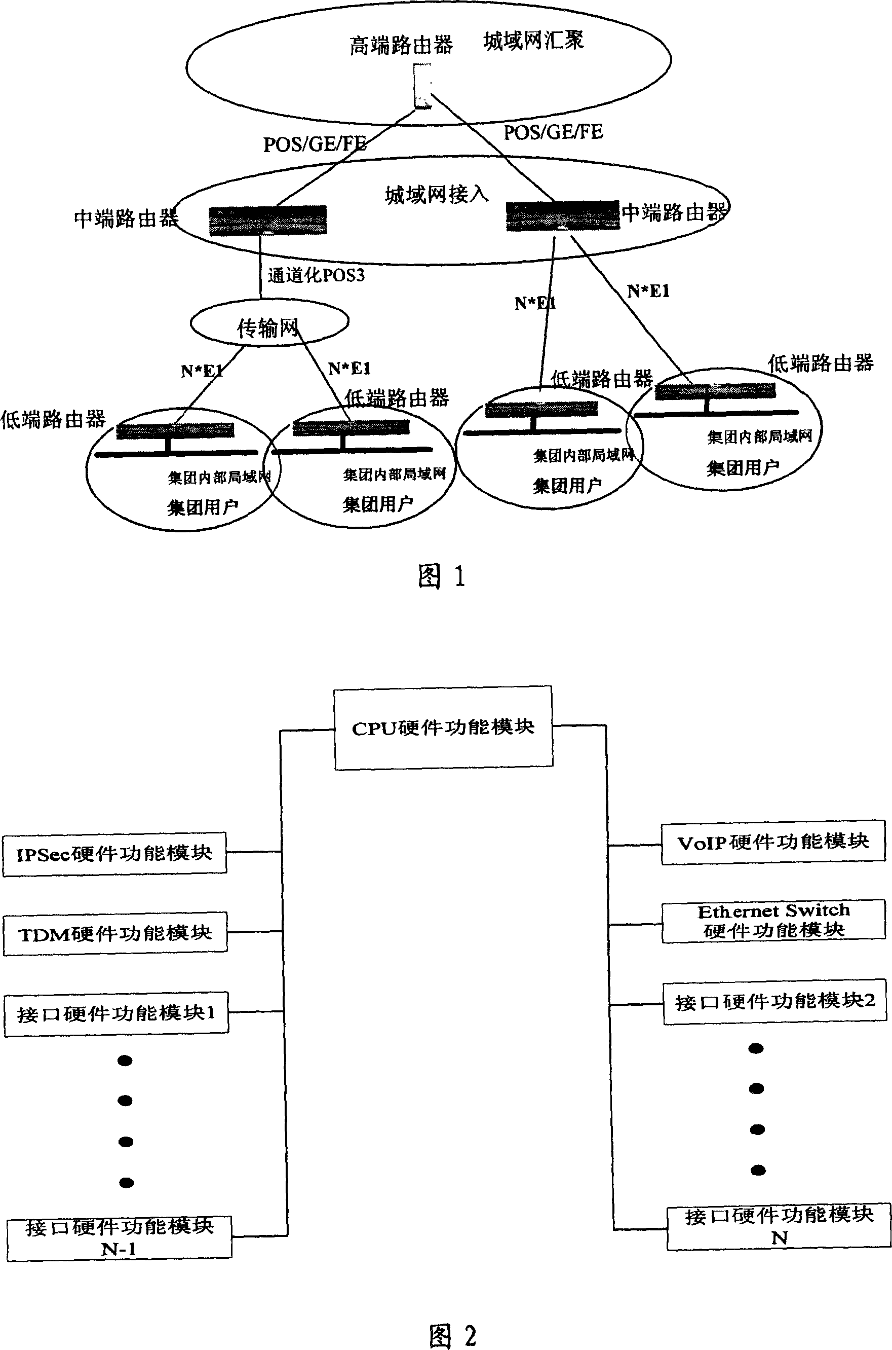
[0027] The method of the present invention relates to a design method of router equipment in a communication or telecommunication system, and proposes to modularize the router equipment in terms of hardware form and software function, and to assemble building blocks according to user needs, so as to meet user functional requirements and The purpose of low cost requirements.
[0028] The basic idea of the present invention is to carry out modular division on the hardware form and software function of the router equipment, and carry out building-block assembly according to user requirements. Specific steps include:
[0029] Step 1: Carry out modular division of router equipment in hardware form;
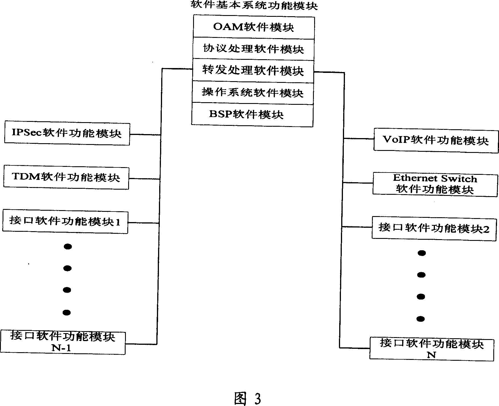
[0030] Step 2: Divide the router software functions into modules;
[0031] Step 3: Carry out building block assembly according to the specific needs of users, realize user function customization, and achieve the purpose of low-cost requirements of users;
[0032] Step 4: Through m...
PUM
 Abstract
Description
Claims
Application Information