

Rolling bearing
A technology for rolling bearings and rolling elements, applied in the field of rolling bearings, can solve problems such as film damage and lower insulation performance of bearings, and achieve the effects of reduced contact stress, easy finishing, and excellent durability
- Summary
- Abstract
- Description
- Claims
- Application Information
AI Technical Summary
Problems solved by technology
Method used
Image

Examples
Embodiment Construction
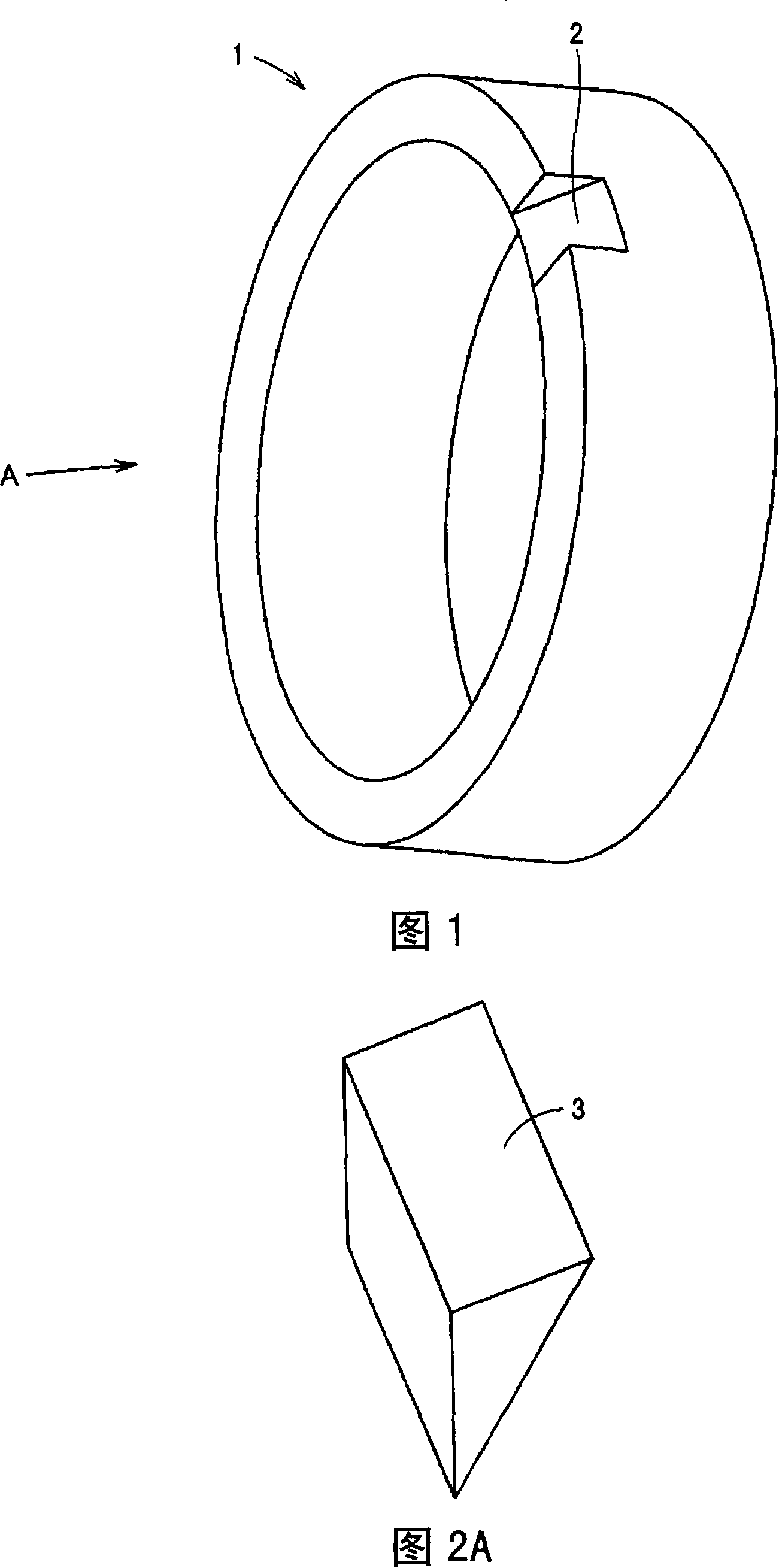
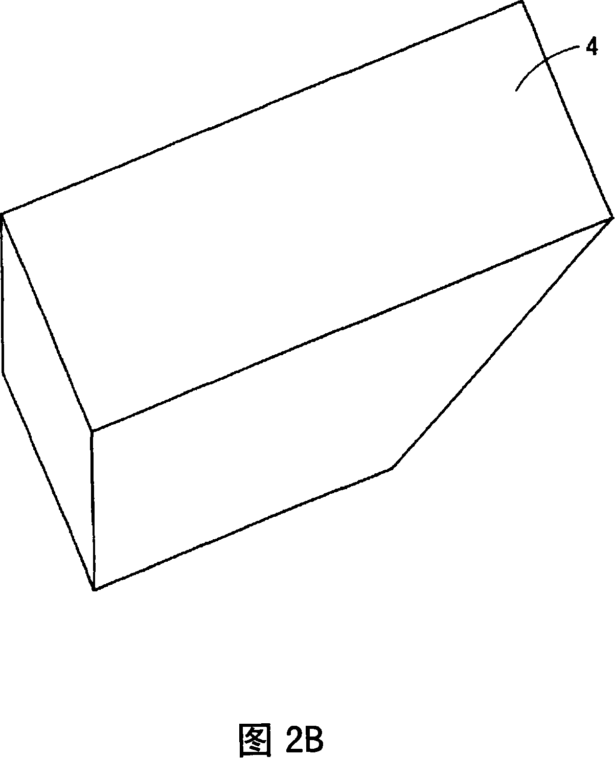
[0032] 4A and 4B are a front view and a side sectional view of a four-point contact ball bearing 11 according to an embodiment of the present invention. In addition, FIG. 5 is a perspective view of the outer ring 13 used in the four-point contact ball bearing 11 shown in FIGS. 4A and 4B . 6A and 6B are perspective views of the keys 16 and 17 for fixing the outer ring 13 to the case.
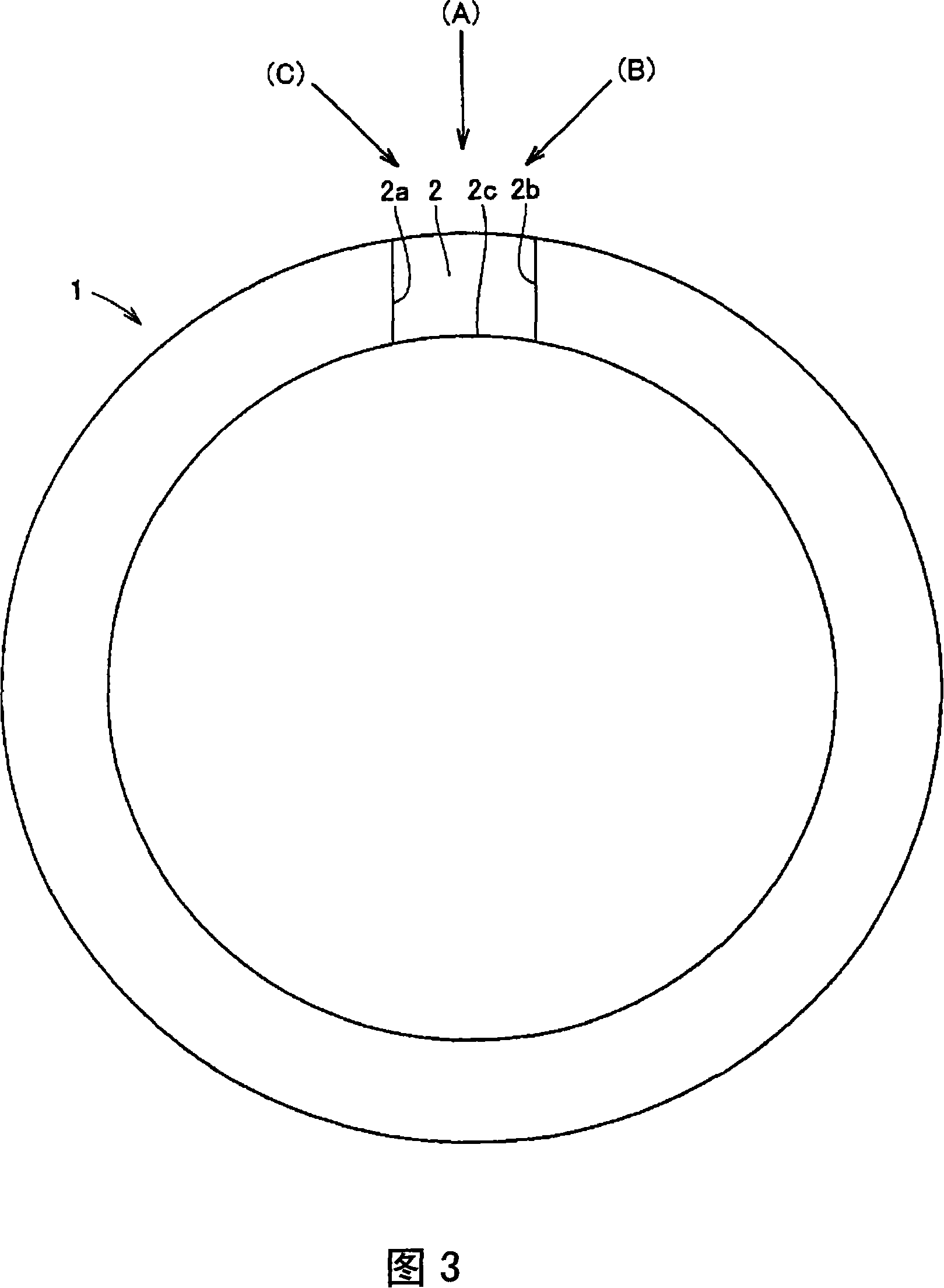
[0033] The four-point contact ball bearing 11 includes, as shown in FIG. 4A , an inner ring 12 , an outer ring 13 , balls 14 serving as rolling elements disposed between the inner ring 12 and the outer ring 13 , and a cage 15 for keeping the distance between the balls 14 . The outer ring 13, as shown in FIG. 5, has a flat surface 13a cut by a plane connecting any point (P) on the outer diameter surface and any two points (Q, R) on the outer peripheral portion of the end surface.
[0034] When assembling the 4-point contact ball bearing 11 with the outer ring 13 as shown in FIG. Creep is thereby...
PUM
 Abstract
Description
Claims
Application Information