Power sliding table for gas and electricity compound transmission

A composite transmission and sliding table technology, applied in non-electric variable control, control using feedback, fluid pressure actuating devices, etc., to achieve the effect of low output power and low cost

Inactive Publication Date: 2008-04-02
杜彦亭
View PDF0 Cites 4 Cited by
  • Summary
  • Abstract
  • Description
  • Claims
  • Application Information

AI Technical Summary

Problems solved by technology

[0002] When mechanical motion equipment is working, it is often necessary to achieve greater output force, higher speed, and position accuracy. At present, it is not easy to achieve linear motion with high drive power, stable speed, high positioning accuracy, small impact, and convenient control. Simple, low cost, easy to realize and other comprehensive performance indicators high requirements

Method used


Image

  • Power sliding table for gas and electricity compound transmission

Examples


Embodiment Construction

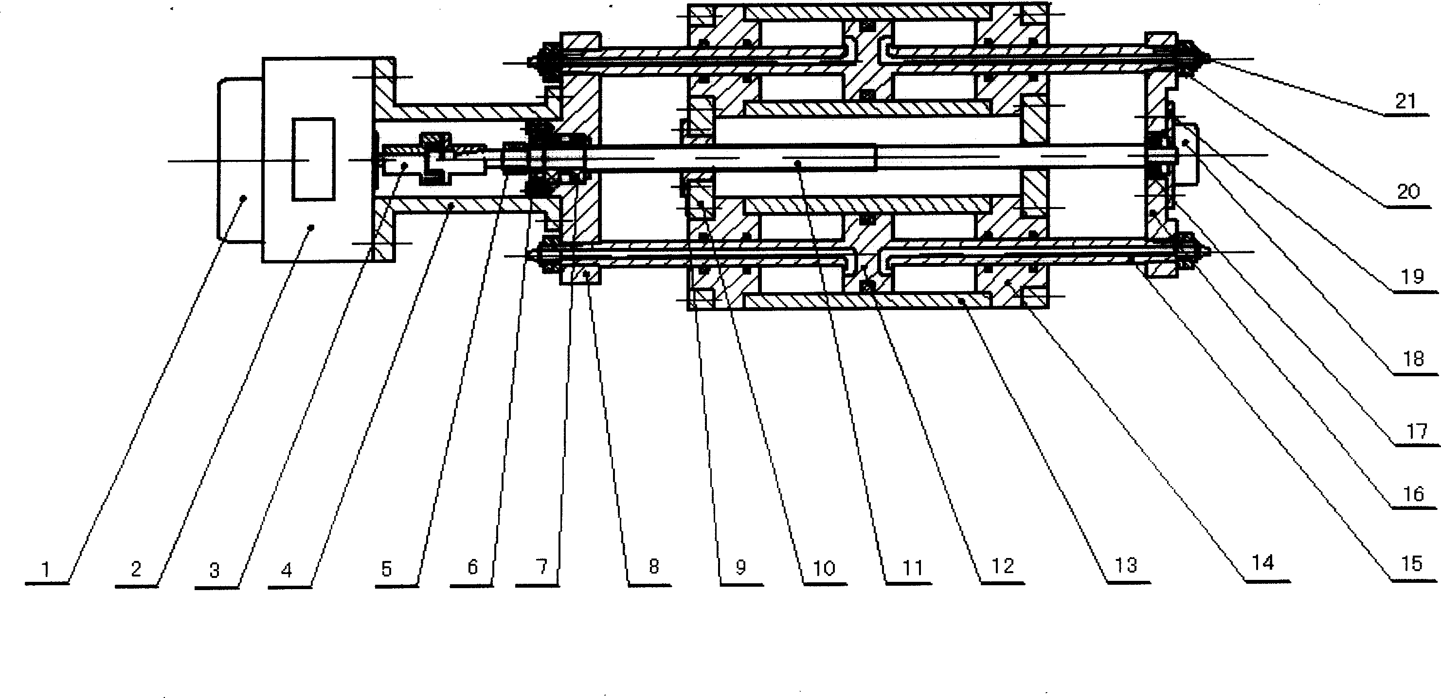
[0018] In the present invention, the piston rods of two ordinary double-rod cylinders are fixedly installed on the supports 8 and 16 of the sliding table seat in parallel, and the two cylinder barrel assemblies 12, 13 are fixed on the sliding table, and a Lead screw nut drive mechanism 9 and 11. The nut 9 is fixed on the slide table, the lead screw is fixed by the bearing group 7, the gland 6, and the double nut 5 on the support 8 of the slide base, and the coupling or reducer 4 for installing the motor is fixed on the support of the slide base, and the motor 2 Fixed on the left end of the coupling 4, the motor 2 and the lead screw 11 are connected by the coupling 3, the electromagnetic brake 1 can be installed on the left end of the motor 2, the stator of the electromagnetic brake 1 is fixed on the shell of the motor 2, the input of the electromagnetic brake 1 The shaft is connected with the shaft of the motor 2, the right end of the leading screw 11 is supported by the beari...


PUM


Abstract

The invention relates to a dynamic slideway capable of straight line motion with an electric and pneumatic composite transmission function. The invention comprises two air cylinders, a screw rod nut driving mechanism, an electromotor, a reducer, an electromagnetic controller and a photoelectric sensor to form a straight line motion driving and controlling unit integrating the factors of liquid, mechanics, electron and optics; the invention can easily achieve the straight line motion speed and the position control with a high comprehensive index.

Description

1. Technical field [0001] The invention relates to a pneumatic and electric composite transmission power slide table with a mechanical mechanism to realize linear motion, especially a linear motion integrated with gas, electricity, machine and light, which utilizes the pressure energy of gas and the mechanical energy output by the motor to jointly realize linear motion. Sporty power slide. 2. Background technology [0002] When mechanical motion equipment is working, it is often necessary to achieve large output force, high speed, and position accuracy. At present, it is not easy to achieve linear motion with high driving power, stable speed, high positioning accuracy, small impact, convenient control, and structure. Simple, low cost, easy to realize and other comprehensive performance indicators high requirements. 3. Contents of the invention [0003] In order to solve the problems in the background technology, the present invention provides a rectilinear motion power sl...

Claims


Application Information

Patent Timeline
Patent Type & Authority Applications(China)
IPC IPC(8): F15B15/00F15B15/16F15B15/22F15B15/28G05D13/00G05D3/12
Inventor 杜彦亭史维祥陈花玲齐铭孙海娟吴博董霞
Owner 杜彦亭
Why Eureka
Try Eureka