

Fan monitoring method and system in multi-field equipment and fan plug-in box
A multi-domain, centralized monitoring technology, applied in general control systems, control/regulation systems, transmission systems, etc., can solve the problems of the failure of the fan being unable to accurately locate the digital quantity of the dry node, and it is difficult to meet the fan monitoring, so as to achieve convenient expansion and monitoring. High ability and efficiency, simple method to achieve the effect
Inactive Publication Date: 2010-11-10
ZTE CORP
View PDF0 Cites 0 Cited by
- Summary
- Abstract
- Description
- Claims
- Application Information
AI Technical Summary
Problems solved by technology
The present invention provides a fan monitoring method, system and fan sub-box in multi-field equipment, which solves the problems in the prior art that faulty fans cannot be accurately located and dry node digital quantities are difficult to meet fan monitoring
Method used
View moreImage
Smart ImageViewing Examples

Examples
Embodiment Construction
Login to View More PUM
 Abstract
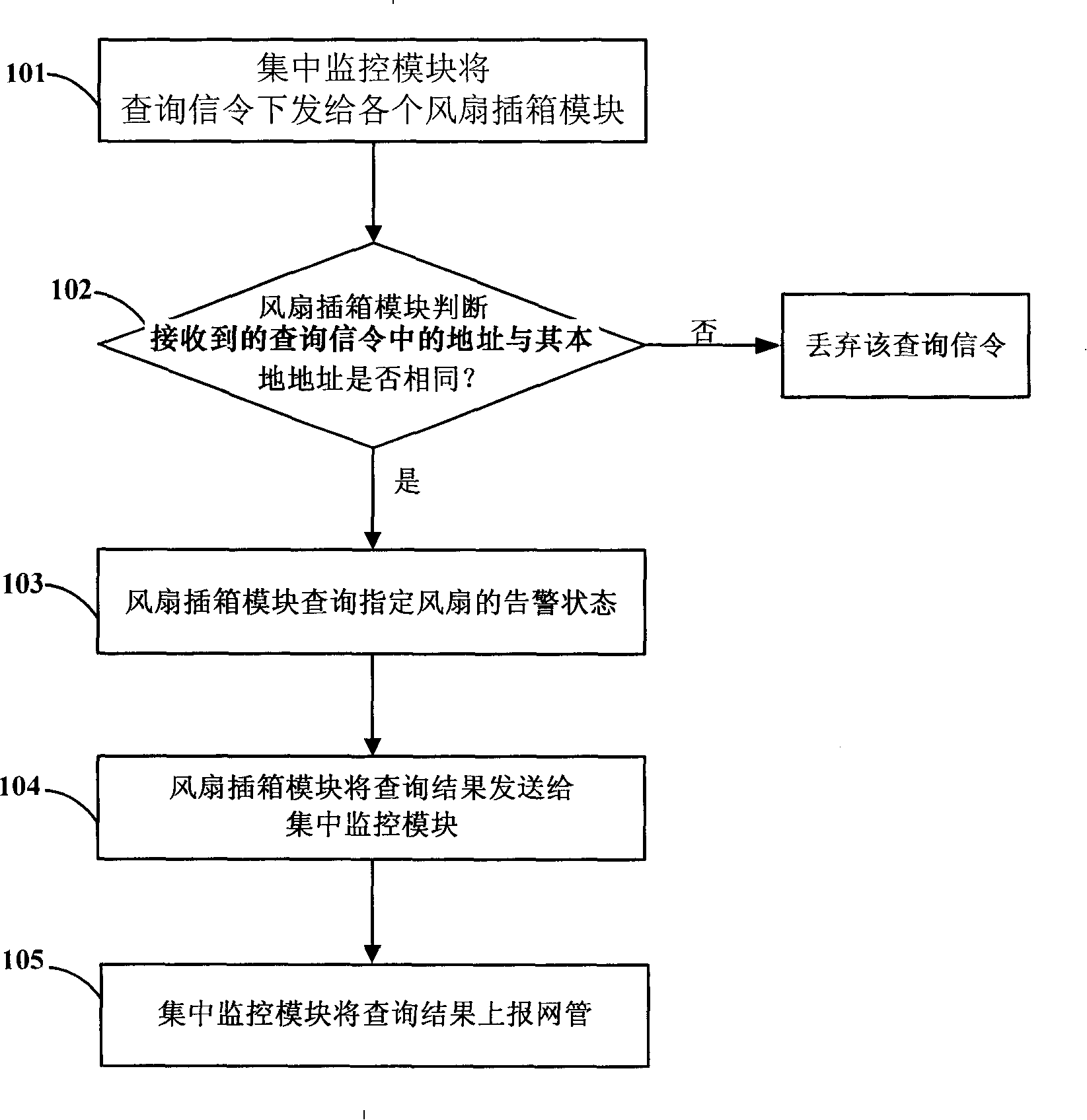
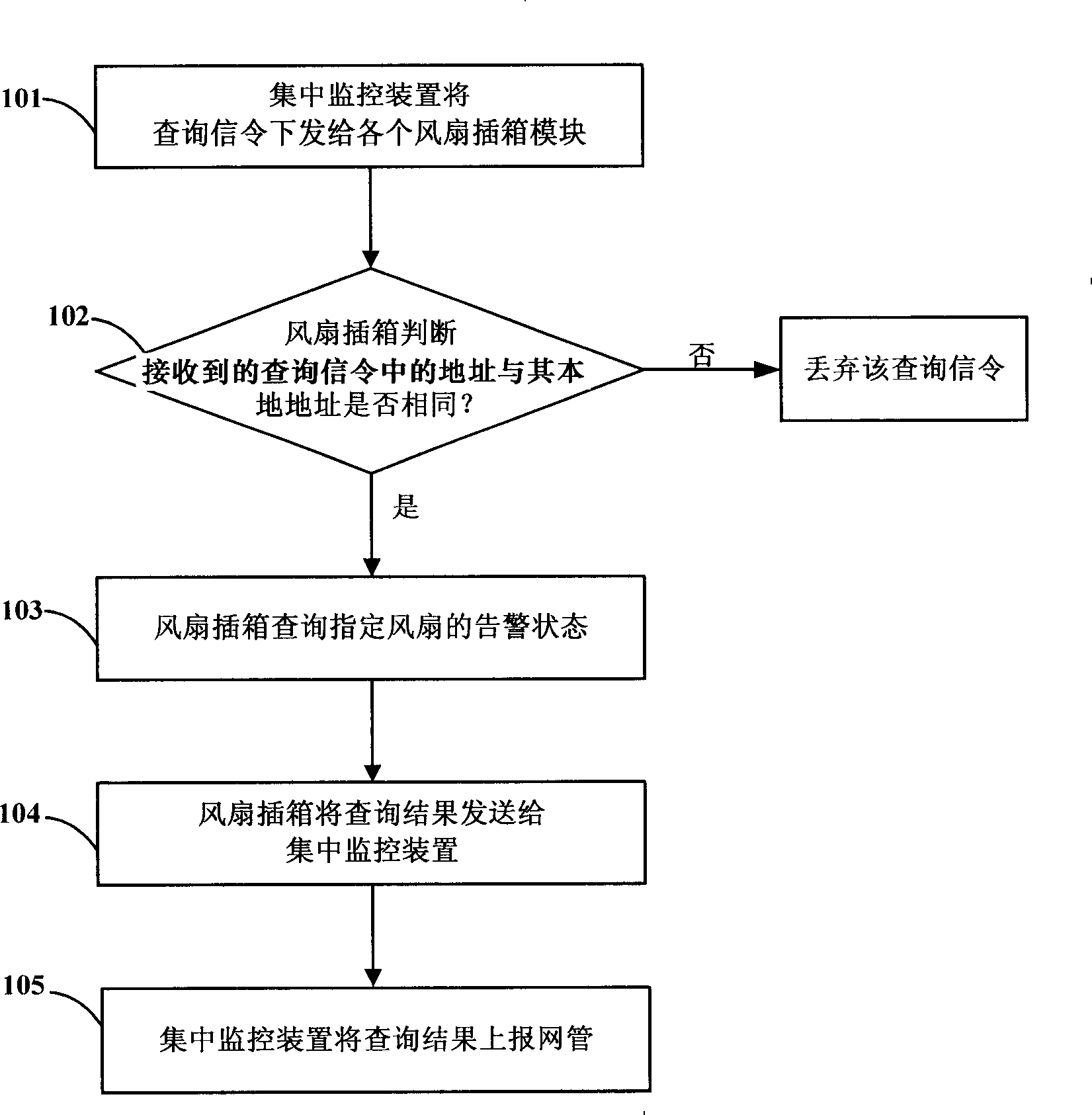
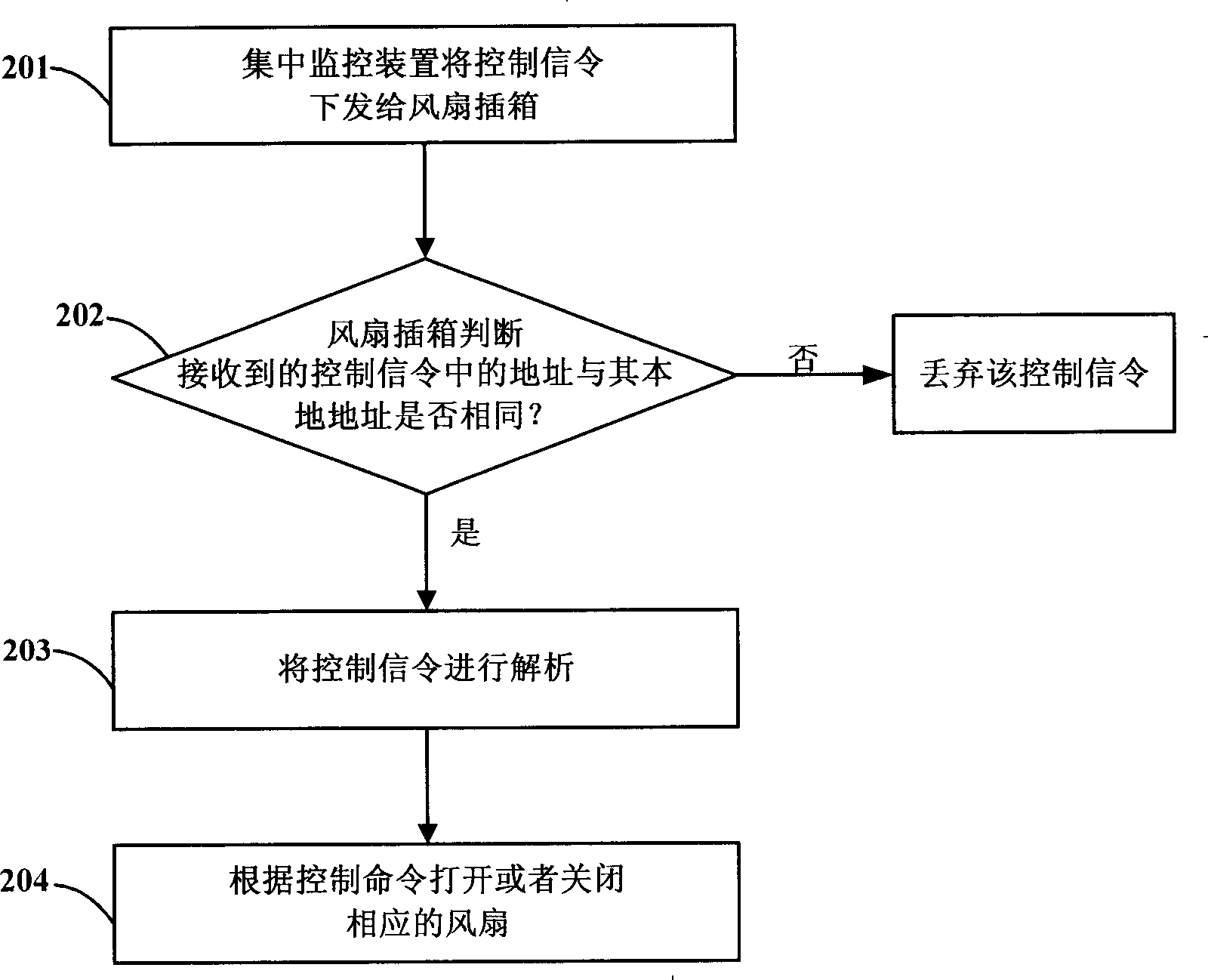
The invention discloses a fan monitoring method in a multi-field equipment, which comprises: (a) a centralized monitoring device sends command to a specified fan through a RS485 bus; (b) according to the received monitoring command, a fan plug box which the specified fan belongs to monitors the specified fan. The invention also discloses a fan monitoring system in a multi-field equipment and a fan plug box. Compared with the prior art, the invention has the advantages that: being able to monitor all fans in the equipment, accurately positioning quantity and position of fault fans; through single RS485 interface, the centralized monitoring device monitors states of all fans, the interface is simple and convenient to be realized, the system source is saved; the expansion is convenient, whenmonitoring fan plug box is required to be added, only hitching the additional fan plug box on the RS485 bus is okay; the monitoring capacity and efficiency are high, the realization method is relatively simple; state controlling of all fans in the access network equipment can also be simply realized.
Description
Method and system for fan monitoring in multi-field equipment, and fan sub-box technical field The invention relates to a fan monitoring method and system, in particular to a fan monitoring method and system in multi-field equipment based on RS485 bus. Background technique In multi-field equipment, especially access network equipment, the Optical Network Unit (ONU) will generate and accumulate a large amount of heat during operation. If the heat is not dissipated in time, it may cause the ONU equipment to work in the long-term A higher temperature will inevitably bring about many problems such as unstable operation of the equipment. If the working environment of the ONU equipment itself is a high-temperature environment, the heat inside the equipment will not be dissipated in time, and the impact will be more obvious. Usually, the ONU device is installed in a relatively remote location, and the environment of the computer room is relatively harsh, so how to effectively sol...
Claims
Login to View More Application Information
Patent Timeline
 Patent Type & AuthorityPatents(China)
IPC IPC(8): H04L29/06G05B19/048G05B19/418
Inventor龚裕钱沛陈卫红
OwnerZTE CORP