Lens barrel and imaging apparatus including the same

A technology of lens barrel and lens group, which is applied in installation, instrumentation, optics, etc., can solve the problems of complex component structure and increase of lens barrel size, and achieve the effect of simplifying structure and reducing lens barrel size

Active Publication Date: 2008-07-23
CANON KK
View PDF0 Cites 9 Cited by
  • Summary
  • Abstract
  • Description
  • Claims
  • Application Information

AI Technical Summary

Problems solved by technology

[0010] In addition, the coupling structure through the cam connection between the focus moving frame and the zoom drive element results in an increase in the size of the lens barrel due to an increase in the size of the cam ring, the components required for the cam connection to be installed, and a complicated component structure

Method used


Image

  • Lens barrel and imaging apparatus including the same
  • Lens barrel and imaging apparatus including the same
  • Lens barrel and imaging apparatus including the same

Examples


no. 1 Embodiment

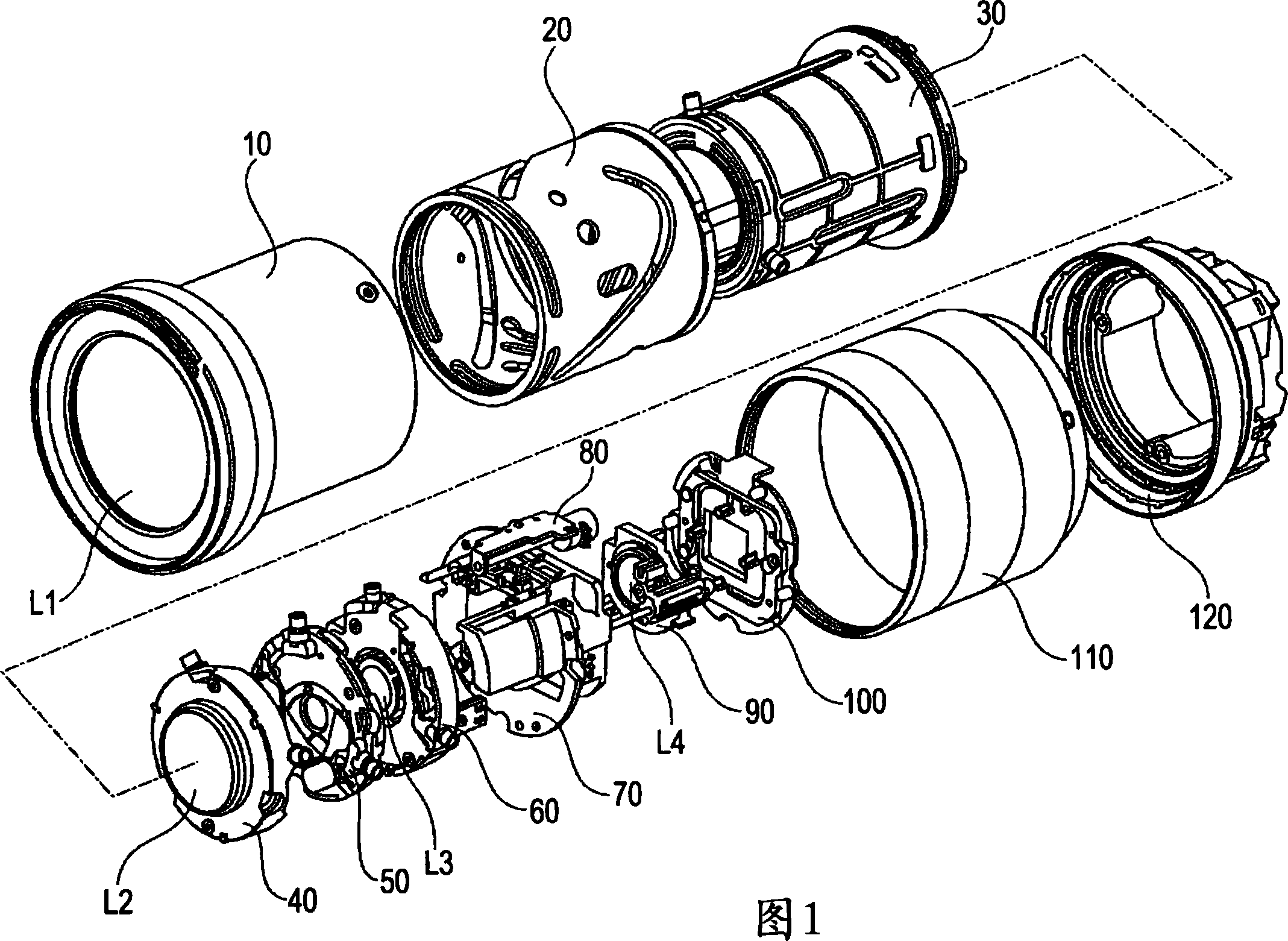
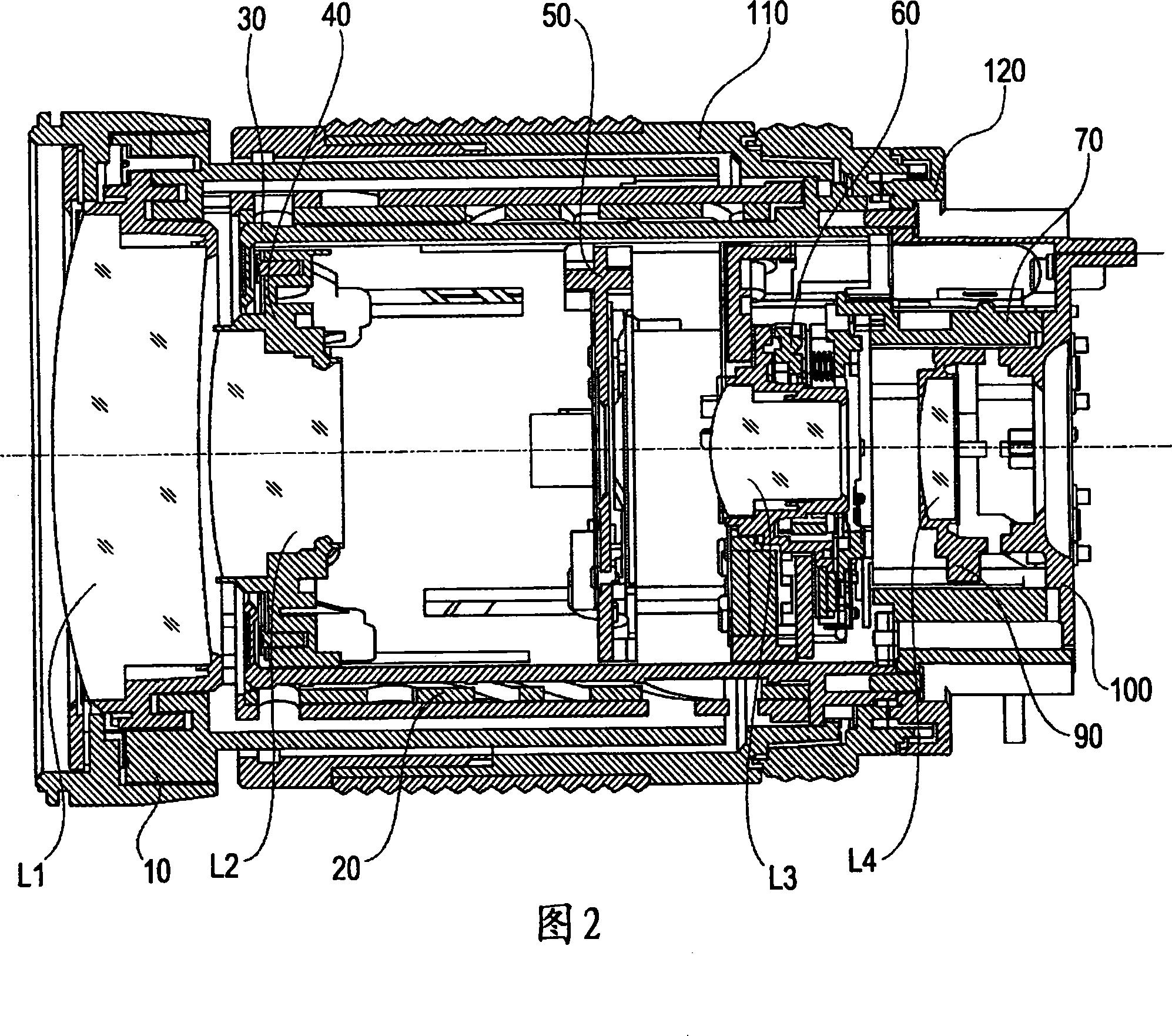
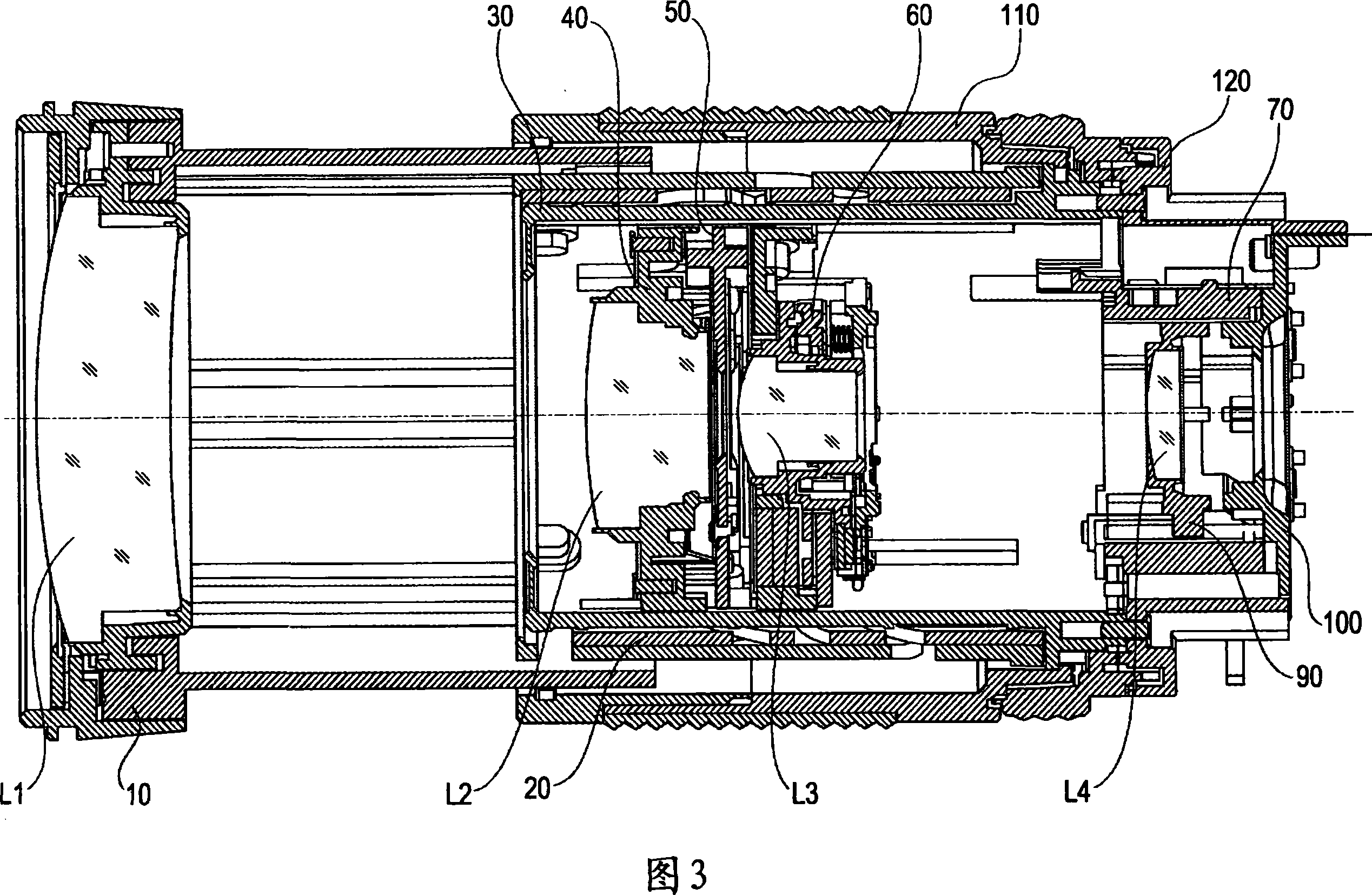
[0027] FIG. 1 is an exploded perspective view showing the structure of a lens barrel used in imaging devices such as video cameras and digital cameras, which is applicable to the present embodiment. 2 and 3 are optical cross-sectional views showing the structure of a lens barrel in an imaging device such as a video camera and a digital camera, which is applicable to the present embodiment. Figure 2 shows the state of each lens group at the wide-angle position. Figure 3 shows the state of each lens group at the telephoto position.

[0028] A lens barrel according to an embodiment of the present invention includes four lens groups. In FIG. 1, lens groups L1, L2, and L3 have a zoom function; L1 is a first zoom lens group, L2 is a second zoom lens group, and L3 is a third zoom lens group. The third zoom lens group L3 moves in a direction substantially perpendicular to the optical axis to optically correct blurred images. The third zoom lens group L3 corresponds to the first len...

no. 2 Embodiment

[0061] 8 and 9 are schematic diagrams showing an improvement in which the tension spring 93 as the urging member in the lens barrel of the first embodiment is replaced with a compression spring 98 .

[0062] The structure of the lens barrel used in imaging devices such as camcorders and digital cameras applicable to the second embodiment, and the overall structure of the focusing lens unit are basically the same as those of the first embodiment, and thus will not be described again here.

[0063] FIG. 8 shows a state in which the focus lens holding member 91 and the image blur optical correction unit 60 are independently driven without interfering with each other. FIG. 9 shows a state in which the focus lens holding member 91 and the image blur optical correction unit 60 interfere with each other.

[0064] The image blur optical correction unit 60 holds the third zoom lens group L3. The focus lens holding member 91 holds the focus lens group L4. The focus lens holding member...


PUM


Abstract

A lens barrel includes a first lens set configured to move manually along an optical axis, a second lens set configured to move electrically along the optical axis, a first holding member configured to hold the first lens set, a second holding member configured to hold the second lens set, a driving member configured to move the second holding member along the optical axis, a transmitting member configured to transmit a driving force of the driving member to the second holding member, and an urging member configured to relatively urge the transmitting member and the second holding member along the optical axis. The first lens set is movable within a range of motion of the second lens set. The urging member is displaced when the second holding member interferes with the first holding member.

Description

technical field [0001] The present invention relates to a lens barrel for, eg, a digital camera, a video camera, and an interchangeable lens barrel, and more particularly, to a lens barrel for manually performing a zooming operation. Background technique [0002] There is currently a rear focus barrel that includes a focus lens that is disposed on the image plane side with respect to the zoom lens and that is configured to correct image plane changes that occur when the zoom lens is moved and to perform focusing operations. [0003] One example of such a lens barrel is a lens barrel that performs zooming by manual operation (manual zoom operation) and focuses by electric operation (autofocus operation) to improve photographing operations. [0004] This embodiment is the lens barrel disclosed in Japanese Patent No. 03514245, which includes peripheral elements disposed within the movement range of the focus movement frame. In this lens barrel, a focus moving frame manually pe...

Claims


Application Information

Patent Timeline
Patent Type & Authority Applications(China)
IPC IPC(8): G02B7/04G02B7/02
Inventor 浅野幸太
Owner CANON KK
Why Eureka
Try Eureka