Method and equipment for automatically controlling track vehicle and lines used for track vehicles

A rail vehicle and vehicle technology, applied in the direction of motor vehicles, electric vehicles, control drives, etc., can solve problems such as inability to guarantee vehicle stop protection

Inactive Publication Date: 2008-10-01
SIEMENS AG
View PDF1 Cites 13 Cited by
  • Summary
  • Abstract
  • Description
  • Claims
  • Application Information

AI Technical Summary

Problems solved by technology

The background for this requirement is that in larger gradients, reliable vehicle s

Method used


Image

  • Method and equipment for automatically controlling track vehicle and lines used for track vehicles
  • Method and equipment for automatically controlling track vehicle and lines used for track vehicles

Examples


Embodiment Construction

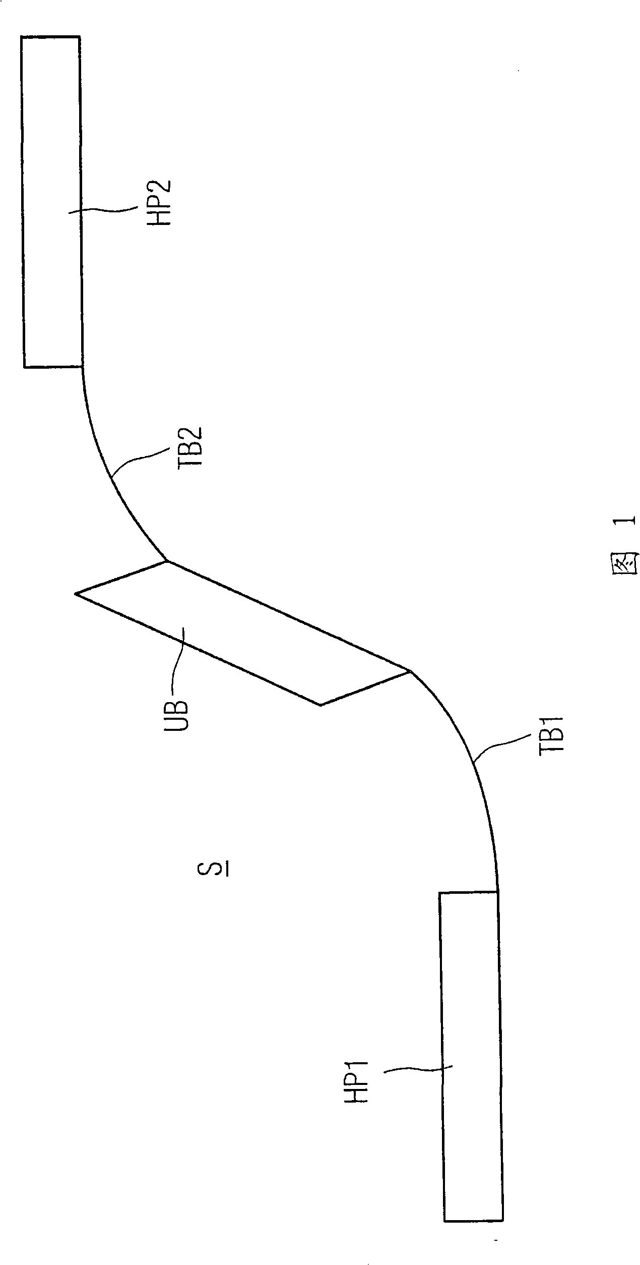
[0032] Fig. 1 shows a first schematic diagram of a route S with a first parking position HP1 and a second parking position HP2 for explaining an embodiment of the method according to the invention. According to the figure, the first parking position HP1 is located in a valley and the second parking position HP2 is located on a hill.

[0033] In the embodiment of FIG. 1 it is assumed that the illustrated route S is the route of a maglev vehicle. If the corresponding maglev vehicle now leaves the first parking position HP1 in the direction of the second parking position HP2, then in the aforementioned method known from DE 38 07 919 A1, the vehicle is required to leave the parking position HP1 The available speed corresponds at least to the minimum speed required to enable the vehicle to reach the second parking position HP2 in the direction of travel when its drive fails.

[0034] It can easily be seen in the schematic illustration of FIG. 1 that the preferred minimum speed can...


PUM


Abstract

The invention provides method and equipment for automatically controlling rail-bound vehicles and tracks for rail-bound vehicles. The method comprising: monitoring and controlling speed of vehicles according to figures of each track such that vehicles move at any time at least with a lowest speed which permits vehicles to arrive in the next parking location (HP2) on the driving direction because of kinetic energy thereof when the driver is conking out. Vehicles travel according to a speed lower than the lowest speed calculated in order to arrive in the next parking location (HP2) on the driving direction when the driver is conking out within a predetermined ramp track interval according to the invention, characterized in that, measurement data aiming at vehicles are collected and analyzed at least in part of regions (TB1, TB2) calculated and determined based on track layout of related track interval. Herein, vehicles are ensured only by analyzing the measurement data aiming at vehicles in the part of regions (TB1, TB2) to implement the safe parking, and protection for vehicles are executed via vehicle braking.

Description

technical field [0001] The invention relates to a method for the automatic control of a rail vehicle moving along a route provided with parking positions, wherein in the method the speed of the vehicle is monitored and controlled according to the profile of the respective route so that the vehicle is moving at least at a certain minimum speed at any time. Speed ​​movement, which minimum speed allows the vehicle to reach the next parking position in the direction of travel due to its kinetic energy when its drive fails. Background technique [0002] A corresponding method is known from the published German patent application DE 38 07 919 A1. This patent describes a safety concept in which the vehicle continues to move to the next parking position in the direction of travel in the event of an emergency or breakdown situation and only stops there. In this case, the speed of the vehicle is monitored and controlled depending on the respective track profile, so that the vehicle r...

Claims


Application Information

Patent Timeline
IPC IPC(8): B60L15/00
CPCB60L2200/26B61L2210/04B61L27/04
Inventor 马库斯·戴米克弗兰克·吉罗德
Owner SIEMENS AG
Why Eureka
Try Eureka