Hot pipe and manufacturing method thereof

A manufacturing method and technology of heat pipes, applied in cooling/ventilation/heating transformation, indirect heat exchangers, lighting and heating equipment, etc., can solve problems such as heat pipe process difficulties, difficult mass production implementation, and reduced liquid delivery capacity

Inactive Publication Date: 2009-01-21
FU ZHUN PRECISION IND SHENZHEN +1
View PDF0 Cites 4 Cited by
  • Summary
  • Abstract
  • Description
  • Claims
  • Application Information

AI Technical Summary

Problems solved by technology

However, these technologies make the manufacturing process of the heat pipe difficult, and the implementation of mass production is not easy, and when the heat pipe is bent or flattened to meet the needs of the applic...

Method used


Image

  • Hot pipe and manufacturing method thereof
  • Hot pipe and manufacturing method thereof
  • Hot pipe and manufacturing method thereof

Examples


Embodiment Construction

[0017] The present invention will be further described below in conjunction with the embodiments with reference to the accompanying drawings.

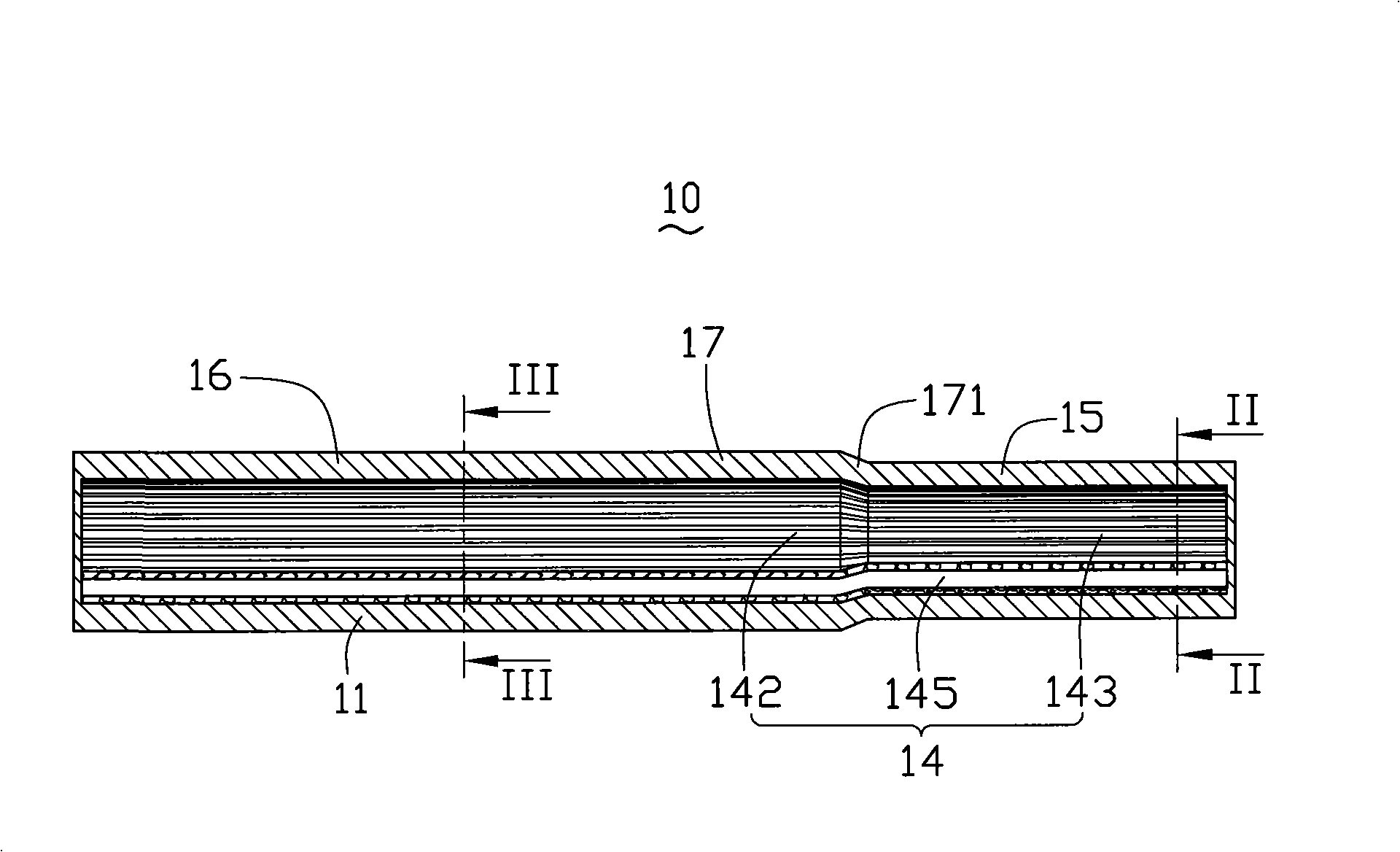
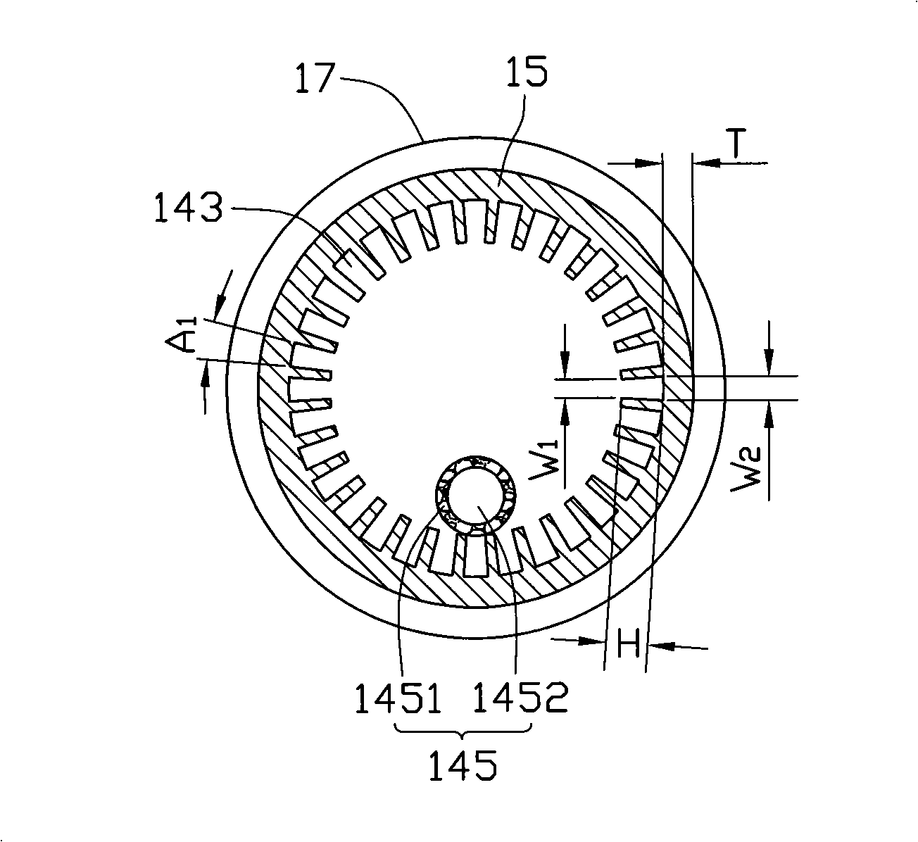
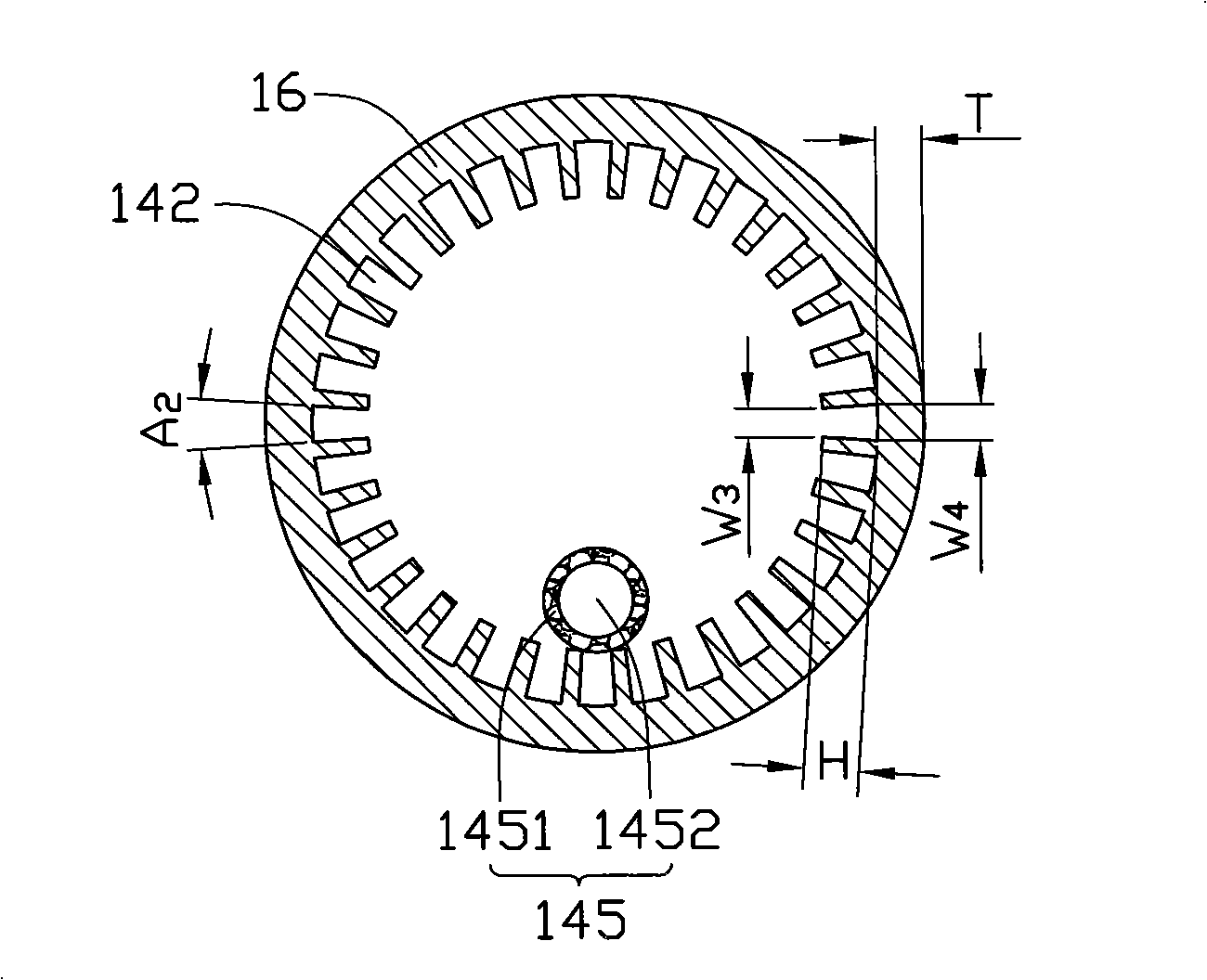
[0018] Figure 1 to Figure 3 Shown is a preferred embodiment of the heat pipe 10 of the present invention, the heat pipe 10 includes a pipe body 11, a capillary structure 14 disposed in the pipe body 11, and an appropriate amount of working fluid (not shown) filled in the pipe body 11 .

[0019] The tube body 11 is a closed hollow metal tube made of copper, aluminum and other materials with good thermal conductivity. The cross section of the tube body 11 is a ring, and its thickness T remains constant Change. The tube body 11 includes an evaporating section 15 and a condensing section 16 located at both ends of the tube body 11 in the axial direction, and an adiabatic section 17 connected between the evaporating section 15 and the condensing section 16 . The pipe diameter (inner diameter and outer diameter) of the evaporating sectio...


PUM


Abstract

A heat pipe comprises a pipe body, a capillary structure in the pipe body and working fluid which is filled in the pipe body, wherein the heat pipe is provided with an evaporating section and a condensing section, the capillary structure comprises a plurality of superfine slots which are arranged on the inner walls of the pipe body, the pipe diameter of the evaporating section is smaller than the pipe diameter of the condensing section, the width of the slot on the evaporating section is smaller than the width of the slot on the condensing section, and the capillary structure further comprises at least a haemal tube which is attached on the inner walls of the pipe body, and a plurality of tiny holes are formed on the walls of the haemal tube, wherein one side of the haemal tube is contacted with the slots, the capillary structure of the heat pipe can provide stronger capillary acting force, and has small liquid reflux resistance, thereby increasing the heat transfer property of the heat pipe. The invention further provides a process for producing the heat pipe, which is convenient for quantity production and application.

Description

technical field [0001] The invention relates to a heat pipe, in particular to a grooved heat pipe and a manufacturing method thereof. Background technique [0002] At present, heat pipes have been widely used in the heat dissipation of electronic components with large heat generation. When the heat pipe works, the low-boiling-point working fluid filled in the pipe body absorbs the heat generated by the heating electronic components in the evaporation section, evaporates and vaporizes, moves to the condensation section with heat, and releases the heat by liquefaction and condensation in the condensation section. The liquefied working fluid flows back to the evaporation section under the action of the capillary structure of the heat pipe wall, and the heat generated by the electronic components is dissipated through the circulating motion of the working fluid. [0003] When the capillary structure of the evaporating section of the heat pipe cannot provide a strong enough capi...

Claims


Application Information

Patent Timeline
IPC IPC(8): F28D15/04H05K7/20
CPCF28D15/046Y10T29/49B23P15/26B23P2700/09
Inventor 张长生王肇浩刘睿凯白先声
Owner FU ZHUN PRECISION IND SHENZHEN
Why Eureka
Try Eureka