V-I switch circuit and programmed control current source using the same

A program-controlled current source and current conversion technology, which is applied in the direction of adjusting electrical variables, control/regulation systems, instruments, etc., can solve the problems of low precision of program-controlled current source, too large volume, and inability to carry out embedded development.

Inactive Publication Date: 2010-06-09
HARBIN INST OF TECH
View PDF3 Cites 0 Cited by
  • Summary
  • Abstract
  • Description
  • Claims
  • Application Information

AI Technical Summary

Problems solved by technology

[0005] The purpose of the present invention is to solve the problem that the output current of the existing voltage-current conversion circuit has a small range of change, cannot be bidirectionally output, and the precision of the programmable current source is low and the volume is too large to carry out embedded development, thereby providing a voltage-current conversion circuit. Current conversion circuit and program-controlled current source using the conversion circuit

Method used


Image

  • V-I switch circuit and programmed control current source using the same
  • V-I switch circuit and programmed control current source using the same
  • V-I switch circuit and programmed control current source using the same

Examples


specific Embodiment approach 1

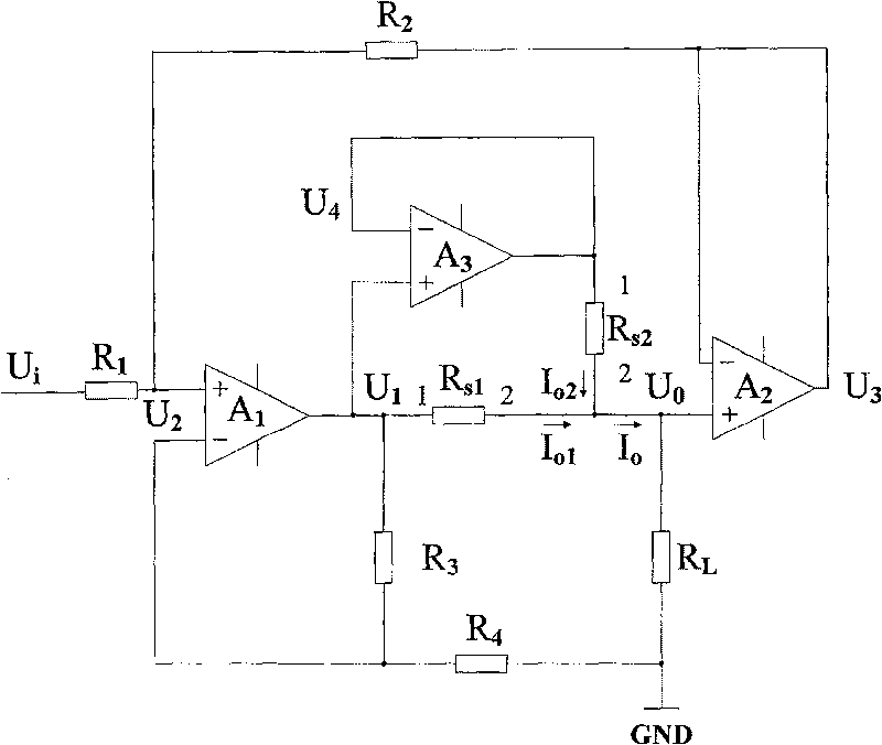
[0030] Specific implementation mode one: combine figure 1 Describe this specific embodiment, a kind of voltage-current conversion circuit, it comprises resistance R 1 , resistance R 2 , resistance R 3 , resistance R 4 , Sampling resistor R S1 , Sampling resistor R S2 , Operational amplifier A 1 , Operational amplifier A 2 and op amp A 3 , resistor R 1One end of the voltage-current conversion circuit is used as the input end of the resistor R 1 The other end of the resistor R 2 One end of the op amp A 1 connected to the positive input, the resistor R 2 The other end of the op amp A 2 The negative input of the operational amplifier and the A 2 connected to the output of the op amp A 1 The output of the operational amplifier A 3 The positive input terminal, resistor R 3 One end and the sampling resistor R S1 Pin 1 is connected to the sampling resistor R S1 pin 2 with the sampling resistor R S2 pin 2 and the op amp A 2 connected to the positive input of the ope...

specific Embodiment approach 2

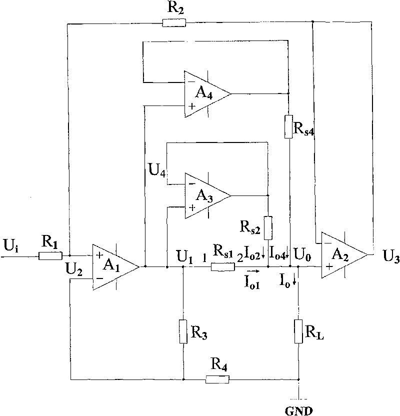
[0031] Specific implementation mode two: combination figure 2 This specific embodiment is described. The difference between this specific embodiment and the first specific embodiment is that it also includes an operational amplifier A 4 and the sampling resistor R S4 , op amp A 4 The positive input of the operational amplifier A 1 connected to the output of the operational amplifier A 4 The negative input terminal with its output terminal and the sampling resistor R S4 One end of the connection, the sampling resistor R S4 The other end of the resistor R S1 2-pin connection.

specific Embodiment approach 3

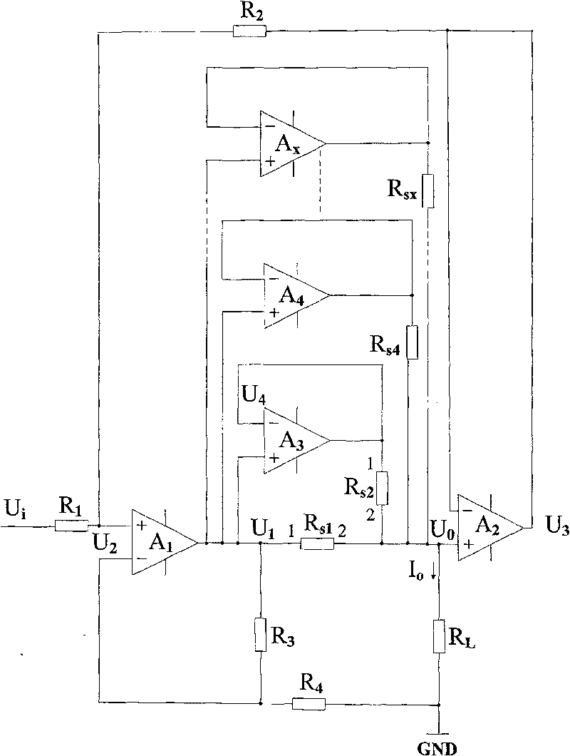
[0032] Specific implementation mode three: combination image 3 Describe this specific embodiment, the difference between this specific embodiment and specific embodiment two is: it also comprises a plurality of operational amplifiers and a plurality of sampling resistors, and the positive input terminal of each operational amplifier is connected with the operational amplifier A 1 The output terminal of each operational amplifier is connected, the negative input terminal of each operational amplifier is connected to its output terminal and one end of a sampling resistor, and the other end of the sampling resistor is connected to the resistor R S1 2-pin connection.


PUM


Abstract

The invention relates to a V-I conversion circuit and a program control current source thereof, belonging to the electronic circuit and the current source technical field, which resolves the problemssuch as the prior V-I conversion circuit has small variation range of output current and can not realize bidirectional output, and the program control current source has low accuracy and can not realize embedded development caused by large volume. In the V-I conversion circuit, the positive input of an operational amplifier A1 is connected with the negative input of an operational amplifier A2 andthe output of the operation amplifier A2 via a resistance R2, the output of the operational amplifier is connected with the positive input of the operational amplifier A3 and is connected with the second pin of a sampling resistance Rs2 via a sampling resistance Rs1 and the positive input of the operational amplifier A2, the negative input of an operational amplifier A3 is connected with its output and the first pin of the sampling resistance Rs2. In a program control current source adopting the V-I conversion circuit, a field programmable gate array via a D / A conversion module is connected with the V-I conversion circuit. The invention is suitable for driving inertia guide devices and measuring the current source output of calibration instruments and the like.

Description

technical field [0001] The invention relates to the fields of electronic circuits and current sources. Background technique [0002] The program-controlled current source is an indispensable instrument for automatic testing and measurement calibration. It is widely used in measuring instruments and automatic verification equipment in industrial and mining enterprises, scientific research and national defense. At present, the program-controlled current source generally adopts the voltage control method, that is, the control voltage is generated first, and then the current output is realized through voltage-current conversion. Due to the differences in control voltage generation methods, voltage-current conversion implementation methods, and output current control methods, there are large differences in the output range and accuracy of current sources. [0003] In motor drives, servo system drives and other equipment that require large currents, power devices such as field ef...

Claims


Application Information

Patent Timeline
Patent Type & Authority Patents(China)
IPC IPC(8): G05F1/10
Inventor 彭宇赵光权刘大同王少军俞洋
Owner HARBIN INST OF TECH
Why Eureka
Try Eureka