Non-contact type actuator

A non-contact actuator technology, applied in the direction of generator/motor, electrostatic generator/motor, electrical components, etc., can solve problems such as large current consumption, high driving voltage, and component wear

Inactive Publication Date: 2009-04-29
SUNONWEALTH ELECTRIC MACHINE IND
View PDF0 Cites 3 Cited by
  • Summary
  • Abstract
  • Description
  • Claims
  • Application Information

AI Technical Summary

Problems solved by technology

[0009] During the operation of the traditional actuator, there are two contact surfaces between the actuator and the substrate 10, one is the contact surface between the rear end of the plate 20 and the substrate 10, and the other is the contact surface between the bushing 21 and the substrate 10. The contact surface between them, and the condition that causes the actuator to have elasti

Method used


Image

  • Non-contact type actuator
  • Non-contact type actuator
  • Non-contact type actuator

Examples


Embodiment Construction

[0021] The structure, characteristics and effects of the present invention will be described in detail by citing the following embodiments in conjunction with the accompanying drawings.

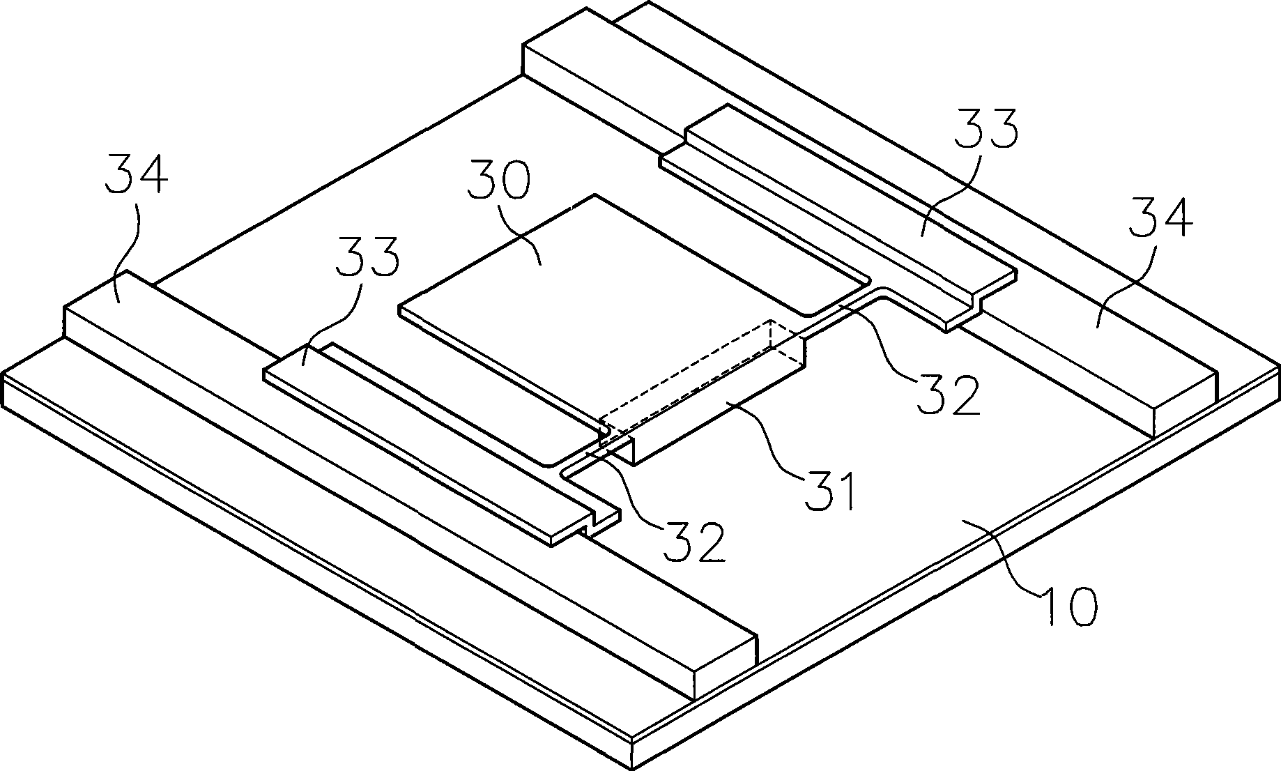
[0022] like figure 2 As shown, the actuator is located on a base plate 10 , which includes a flat plate 30 , a bushing 31 , at least two support beams 32 , at least two sliding seats 33 and at least two rails 34 .

[0023] Wherein, the two tracks 34 are located above the substrate 10 and can be straight or curved, and the two tracks 34 are arranged at equal intervals, such as two straight lines parallel to each other or two concentric circles.

[0024] The two sliding seats 33 are respectively straddled on the two rails 34, and the two sliding seats 33 respectively extend with supporting beams 32, and the supporting beams 32 are also connected with the flat plate 30, and the adjoining parts of the supporting beams 32, the sliding seats 33 and the flat plate 30 are all formed There are chamf...


PUM

PropertyMeasurementUnit
Lengthaaaaaaaaaa
Widthaaaaaaaaaa

Abstract

The invention relates to a non-contact typed actuator which is arranged on a substrate, comprising a slab and a bushing; the non-contact typed actuator is characterized in that the ratio of the length and the width of the slab is from 0.55 to 0.59. When an external voltage is added, although the slab is bent for being attracted by the substrate, the slab is not contacted with the substrate. As no friction force between the slab and the substrate exists, the non-contact typed actuator only needs to apply extremely small voltage and consume minimum current to resist the reaction force generated by the attraction of static force of the slab and to carry out the bouncing action by an elastic tensile force generated when the slab recovers from a bent state; therefore, the non-contact typed actuator can reduce the driving voltage, reduce the electricity consumption and the abrasion of the component so as to prolong the service life.

Description

technical field [0001] The invention relates to a non-contact actuator. By increasing the bending rigidity of the plate, it avoids the contact between the plate and the substrate when it is attracted by the substrate, so as to reduce frictional resistance, reduce driving voltage, reduce current consumption, and reduce component wear to prolong the life of the actuator. life. Background technique [0002] The micro fan (Micro Fan) consists of two parts, one is a micro fan blade made of self-assembly technology (Self-assembly), and the other is a micro motor (micro-actuator) composed of a micro-actuator (Micro-actuator). Micro Motor). [0003] Among them, the action principle of the micro-actuator (Micro-actuator) is as follows: figure 1 Shown: [0004] The microactuator includes a substrate 10, the substrate 10 is generally a silicon substrate (Silicon Substrate), and coated with a silicon nitride (Silicon-Nitride) insulating film with a thickness of about 0.6 microns; the...

Claims


Application Information

Patent Timeline
IPC IPC(8): H02N1/00
Inventor 洪银树黄义佑
Owner SUNONWEALTH ELECTRIC MACHINE IND
Why Eureka
Try Eureka