Microwave low-waveband submicron microstrip duplexer

A low-band, duplexer technology, applied in waveguide-type devices, connecting devices, electrical components, etc., can solve the problems of difficult integration, high processing cost, low production efficiency, etc., and achieve good input and output standing wave ratio, circuit Good consistency and compact structure

Inactive Publication Date: 2009-05-20
SHENZHEN GRENTECH CO LTD +1
View PDF0 Cites 4 Cited by
  • Summary
  • Abstract
  • Description
  • Claims
  • Application Information

AI Technical Summary

Problems solved by technology

The traditional duplexer is mainly composed of cavity filters, and the duplexer composed of cavity filters has the d

Method used


Image

  • Microwave low-waveband submicron microstrip duplexer
  • Microwave low-waveband submicron microstrip duplexer

Examples


Embodiment Construction

[0009] The present invention will be described in detail below with reference to the accompanying drawings and examples. However, the invention is not limited to the examples given.

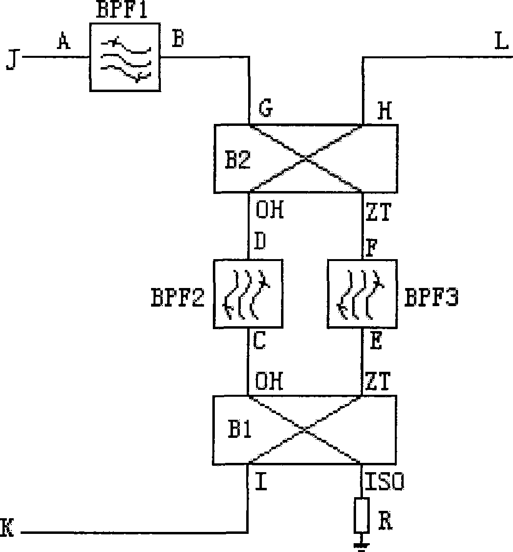
[0010] Such as figure 1 As shown, the circuit composition of the microstrip duplexer of the present invention includes three microstrip bandpass filters BPF1, BPF2, BPF3 and two 3dB orthogonal bridges B1, B2, the B end of the first filter BPF1 is connected to the first The input and output interface G of the bridge B1 is connected, and its passband frequency is different from that of the second and third filters BPF2 and BPF3. The passband frequencies of the second and third filters BPF2 and BPF3 are the same, and are connected to the first Between the coupling terminal OH and the through terminal ZT of the bridge B1, the second bridge B2: the D terminal of BPF2 is connected to the OH terminal of B1, the C terminal of BPF2 is connected to the OH terminal of B2, and the F terminal of BPF3 is conn...


PUM

PropertyMeasurementUnit
Thicknessaaaaaaaaaa

Abstract

The invention discloses a microwave low-band ultra-micro micro-strip diplexer. A circuit composition of the microwave low-band ultra-micro micro-strip diplexer comprises three micro-strip band-pass filters and two 3dB quadrature bridges, one end of a first filter is connected with an input/output interface of a first bridge, the pass-band frequency of the first filter is different from those of a second filter and a third filter, the pass-band frequencies of the second filter and the third filter are same, and the second filter and the third filter are parallelly connected between coupling ends and straight-through ends of the first bridge and a second bridge. The micro-strip diplexer is formed by the micro-strip band-pass filters with good selectivity and the 3dB quadrature bridges with functions of signal decomposition, synthesis and reflection. The micro-strip diplexer has good input/output standing wave ratio, circuits are easy to be in cascade connection with pre-stage and post-stage circuits, ultra-fine micro-strip thin-film technology is adopted, and the circuits have good consistency, compact structure and small volume, thereby ensuring that the microwave low-band ultra-micro micro-strip diplexer has high selectivity and high integration level and is widely applied to the technical field of communication.

Description

Technical field: [0001] The invention relates to a microstrip duplexer used in the field of microwave communication, in particular to a high-selectivity, high-integration ultra-miniature microstrip duplexer for microwave low-band. Background technique: [0002] The duplexer is widely used in the field of communication technology. It enables two frequency bands with a certain interval to obtain greater isolation, so as to facilitate two-way signal transmission and reception. The traditional duplexer is mainly composed of cavity filters, and the duplexer composed of cavity filters has the disadvantages of bulky, complex structure, difficult integration, high processing cost, and low production efficiency. Invention content: [0003] The technical problem to be solved by the present invention is to overcome the shortcomings of existing duplexers and provide a microwave low-band ultra-miniature microstrip duplexer with high selectivity and high integration. [0004] The techn...

Claims


Application Information

Patent Timeline
IPC IPC(8): H01P1/20H01P5/12
Inventor 庄昆杰傅阳波
Owner SHENZHEN GRENTECH CO LTD
Why Eureka
Try Eureka