Multi-stage pressure regulating conversion tap switch

A tap changer and phase conversion technology, which is used in output power conversion devices, transformers, and conversion equipment that can be converted into DC without intermediate conversion. Can not have the problem of multi-level fine adjustment of output voltage

Active Publication Date: 2012-03-21
SHENYANG HONGJI ELECTRICAL
View PDF3 Cites 0 Cited by
  • Summary
  • Abstract
  • Description
  • Claims
  • Application Information

AI Technical Summary

Problems solved by technology

However, with the development and perfection of my country's power grid, the requirements for power supply quality have also been raised to a higher level, especially the stability of power supply is becoming more and more stringent, the voltage regulation of transformers is becoming more detailed, and the tap changer must realize multiple Level voltage regulation conversion function, but the above patented series of tubular switches are difficult to achieve this level:
[0003] 1. The series of tubular switches only have Y-D conversion, and it is not possible to make finer adjustments to the multi-level voltage during the Y-D conversion process of the voltage regulation mode.
[0004] 2. The positive and negative switching of the series tube type switch can only achieve 5 taps at most objectively for the taps of the voltage regulating coil of the transformer, because the rule of the circumferential arrangement of the fixed contacts in the tube type tap changer is twice the number of taps. times, 5 taps need to arrange 10 positions of fixed contacts in the circumferential direction
[0005] 3. The tubular switch of the above-mentioned patented product series has no coarse and fine adjustment structure, let alone multi-level fine adjustment of the output voltage during the coarse-level conversion of the voltage regulation method

Method used


Image

  • Multi-stage pressure regulating conversion tap switch
  • Multi-stage pressure regulating conversion tap switch
  • Multi-stage pressure regulating conversion tap switch

Examples


Embodiment Construction

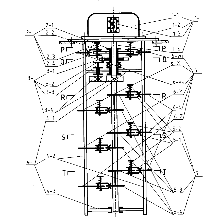
[0042] Three specific ways of the embodiment of the present invention will be further described below in conjunction with the accompanying drawings, as figure 1 Shown is a simplified structural diagram of an embodiment of a three-phase 9-stage voltage regulating tap-changer. The upper part of the tap-changer is the operating mechanism 1-, and its main components are: 1-1 is the mechanism box, which controls the tap-changer to press It is designed to run regularly; 1-2 is the bottom plate, so that the tap changer is installed in the working position of the transformer box without leakage; 1-3 is the gear position display window, indicating the gear position of the tap changer in the 9-level voltage regulation ; 1-4 is the transmission shaft, which transmits the regular operation power of the tap changer.

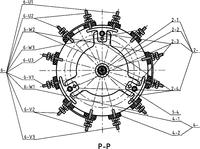
[0043] figure 2 shown as figure 1 The structural schematic diagram of the P-P section in the top view focuses on the conversion mechanism 2- that changes the pressure regu...


PUM


Abstract

The invention discloses a multi-stage voltage regulation conversion tapping switch, which aims to solve key technology that the multi-stage voltage regulation is added during the conversion of the switch with a plurality of voltage regulation modes such as Y-D conversion, positive and reverse voltage regulation conversion, and coarse and fine voltage regulation conversion. The invention adopts a unique technical proposal that a conversion mechanism 2- with intermittent movement period is adopted, and is in infinite cyclic switching connection with conversion fixed contacts of various related phases of a tap of a coil of a transformer to achieve that the operation law of the conversion mechanism follows the conversion of an alternate and periodic voltage regulation mode and the multi-stagevoltage regulation is performed in a periodic conversion interval. The main use of the switch is that the multi-stage voltage regulation conversion tapping switch is applicable to various same grade transformers with different voltage regulation modes, achieves multiple use, and fills the gap that prior art series pipe-type tapping switches have no a coarse and fine voltage regulation mode.

Description

technical field [0001] The invention relates to a voltage regulating device for power transformers, which is a further improvement on the existing tap changer, and achieves multiple functions in one machine, and is suitable for Y-D conversion, positive and negative adjustment conversion, coarse and fine adjustment conversion and multiple different voltage regulation methods at the same time Class transformers, and the same multi-level voltage regulation special purpose can also be carried out in the voltage regulation mode conversion cycle interval. Background technique [0002] Patent No. ZL03262313.5 is named non-excitation tube switch, patent No. ZL03264293.8 is named non-excitation tube switch with inner tube extraction structure, patent No. ZL200320100539.1 is named fixed contact of non-excitation tube tap changer The array and other Chinese patents have innovated the unique structure of a series of tubular switches, so that the three-phase linkage tubular structure tap...

Claims


Application Information

Patent Timeline
Patent Type & Authority Patents(China)
IPC IPC(8): H01F29/04H02P13/06H01H1/56
Inventor 任世灵
Owner SHENYANG HONGJI ELECTRICAL
Why Eureka
Try Eureka