

Field element
A magnetic field and component technology, applied in electrical components, magnetic circuit rotating parts, magnetic circuits, etc., can solve problems such as magnet demagnetization, and achieve the effects of preventing demagnetization, reducing demagnetization, and increasing the area of magnetic poles
- Summary
- Abstract
- Description
- Claims
- Application Information
AI Technical Summary
Problems solved by technology
Method used
Image

Examples
no. 1 approach
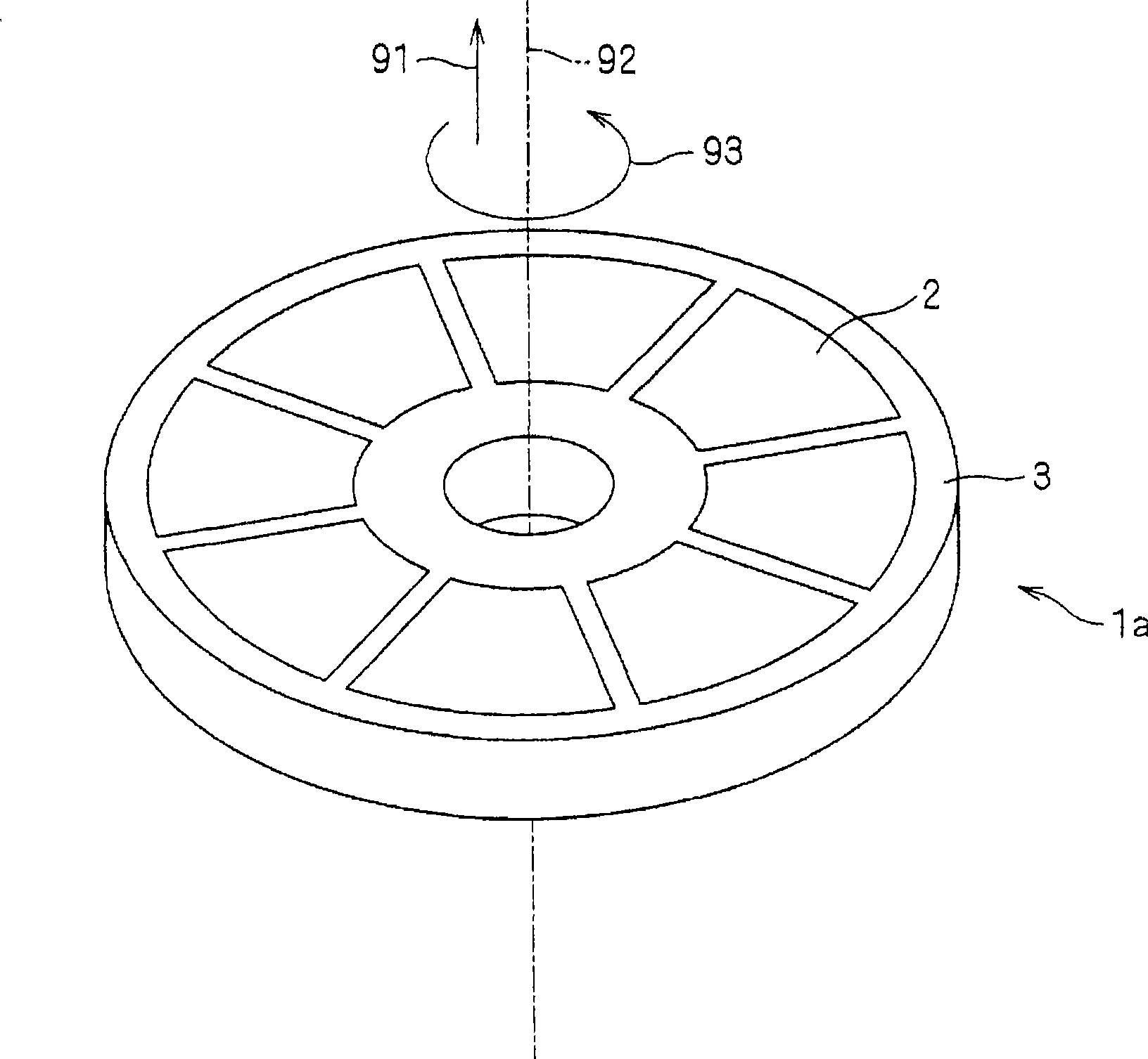
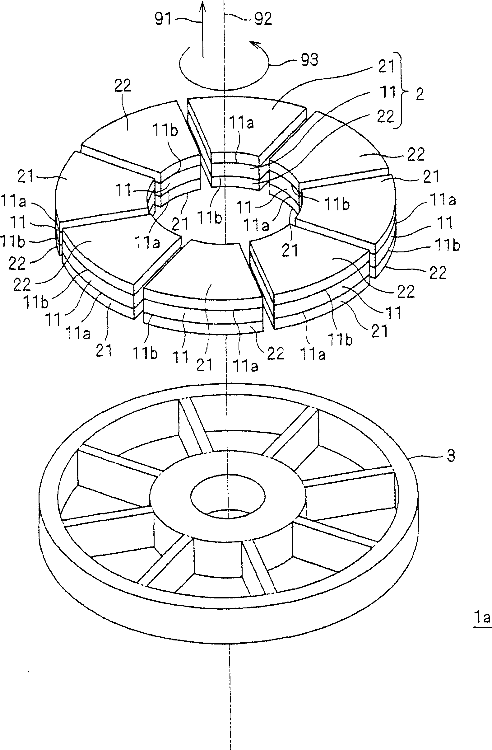
[0062] figure 1 and figure 2 All schematically show the same field element 1a according to this embodiment. The field element 1 a has a field section 2 and a connection section 3 , and is rotatable around a rotation axis 92 extending along a predetermined direction 91 . In addition, in figure 2 In , the magnetic field part 2 and the connection part 3 are shifted and shown along the rotation axis 92 .
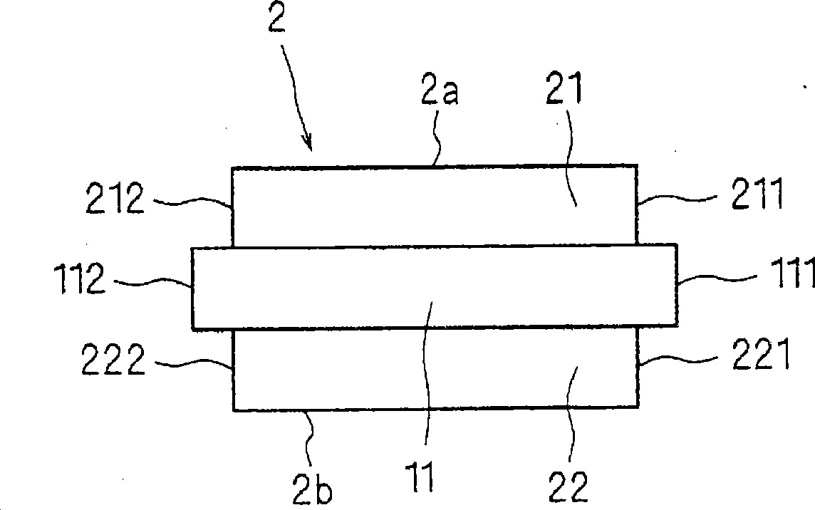
[0063] The magnetic field unit 2 has a magnet 11 and magnetic plates 21 and 22 . The magnet 11 has a first magnetic pole surface 11 a and a second magnetic pole surface 11 b having mutually different polarities in a predetermined direction 91 . For example, the first magnetic pole surface 11a has an N pole, and the second magnetic pole surface 11b has an S pole.
[0064] The magnet 11 is preferably a sintered rare earth magnet. This is because the rare earth magnet has a large magnetic flux density. In this case, eddy current loss tends to occur in the rare earth magnet...
no. 2 approach
[0090] Figure 8 and Figure 10 The field elements 1b and 1c according to the present embodiment are schematically shown, respectively. The field elements 1b and 1c have the field part 2 and the connection part 3 similarly to the field element 1a. In addition, in Figure 8 and Figure 10 In , the magnetic field part 2 and the connection part 3 are shifted and shown along the rotation axis 92 . Hereinafter, points different from the field element 1 a described in the first embodiment will be described. In addition, in Figure 8 and Figure 10 In the above, the case where the magnetic plates 21 and 22 are respectively provided on the magnetic pole surfaces 11a and 11b of the same magnet 11 is shown about the magnetic field part 2, but it is not limited to this as in the first embodiment.
[0091] Figure 9 and Figure 11 A section through the field elements 1b, 1c with respect to the circumferential direction 93 is shown in each case. In any of the field elements 1b, 1...
no. 3 approach
[0104] Figure 14 A field element 1d according to this embodiment is schematically shown. The field element 1 d has a field portion 2 , a connection portion 3 , and a magnetic core 5 . The magnetic field unit 2 is the same as the first embodiment ( figure 1 etc.) are constructed in the same way.
[0105] The magnetic core 5 is provided between the magnetic field portions 2 adjacent in the circumferential direction 93 so as to be separated from the magnetic field portions 2 . In addition, it is preferable to use a dust core for the magnetic core 5 . This is because the eddy current loss generated in the magnetic core 5 can be reduced.
[0106] Magnetic core 5 may also be a member in which electromagnetic steel sheets are laminated. From the viewpoint of reducing iron loss, it is preferable to use a member in which electromagnetic steel sheets are laminated in the circumferential direction 93 . It is not preferable to use a member in which the magnetic steel sheets are lam...
PUM
 Abstract
Description
Claims
Application Information