Oscillating device for brush breaker

A swing device and brush cutter technology, which is applied to the chassis of agricultural machinery, agricultural machinery and implements, and hedge trimming equipment, etc., can solve the problem that the working width cannot be adjusted, the suspension position cannot be adjusted horizontally, and the brush cutter cannot be adjusted. Operation and other problems, to achieve the effect of improving cutting efficiency, improving operation efficiency and flexible operation

CN101563976AActive Publication Date: 2009-10-28常州汉森机械股份有限公司
0 Cites 8 Cited by

Patent Information

Authority / Receiving Office
CN · China
Current Assignee / Owner
Publication Date
2009-10-28

Smart Images

  • Figure 1
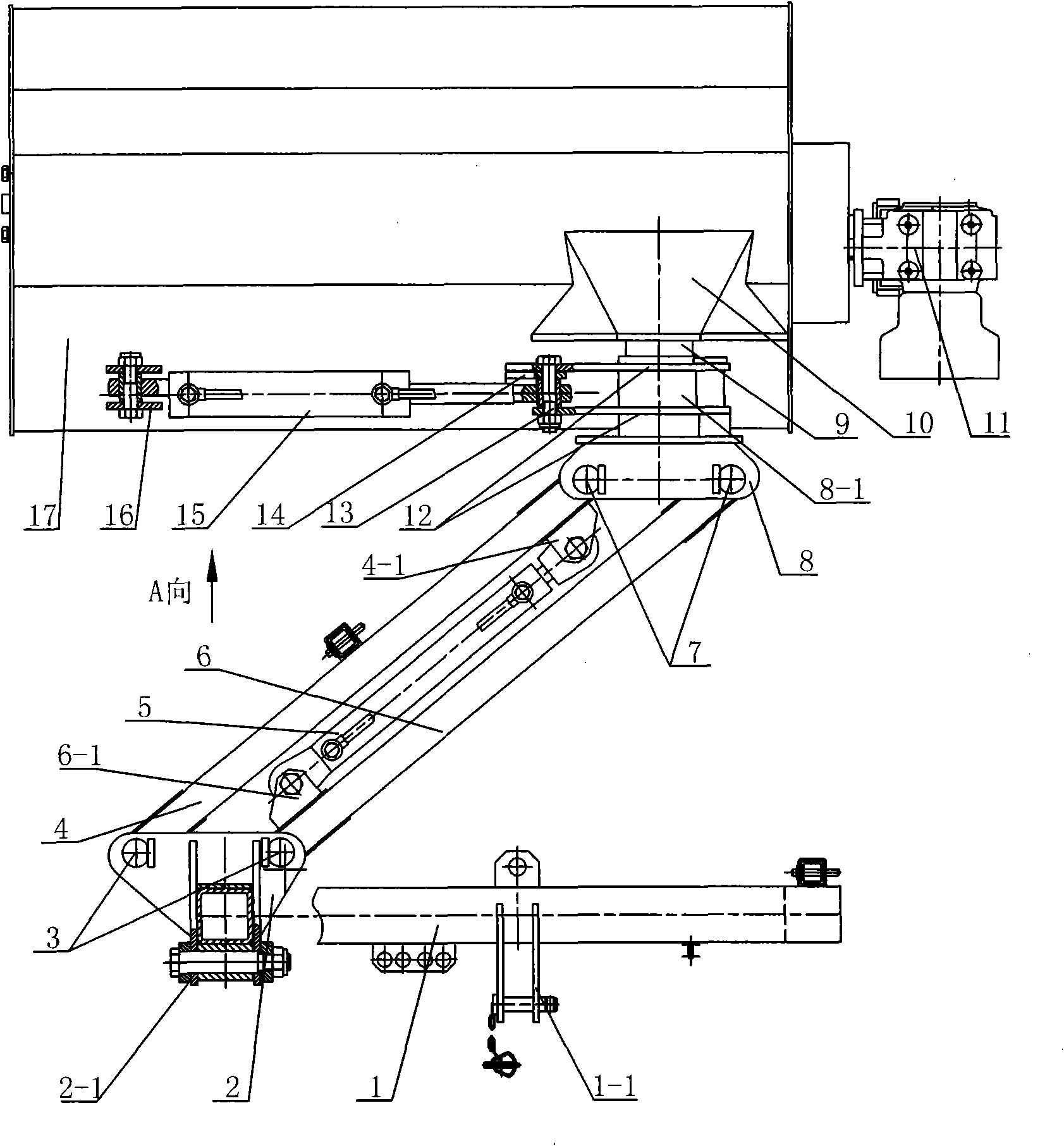
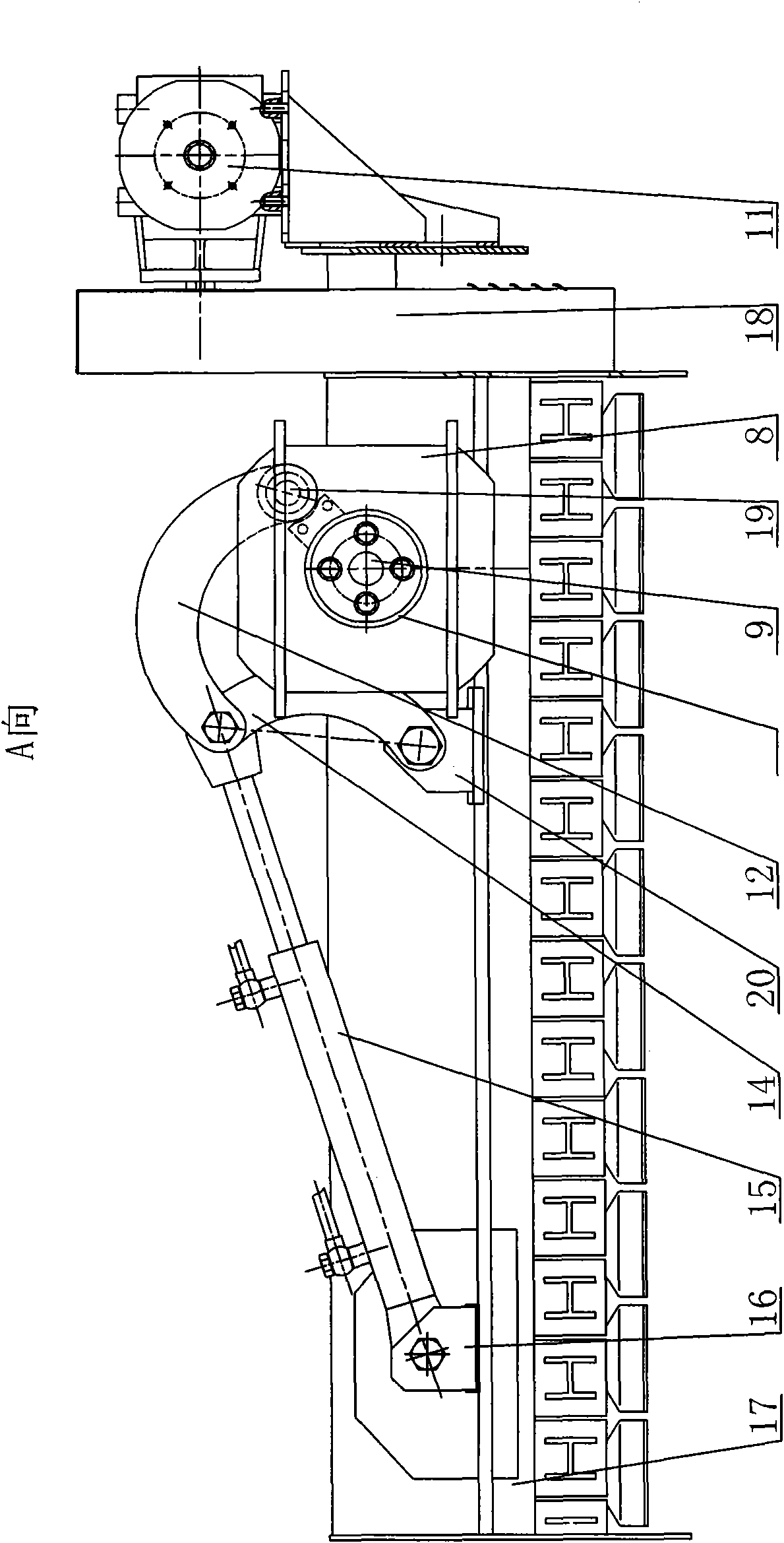
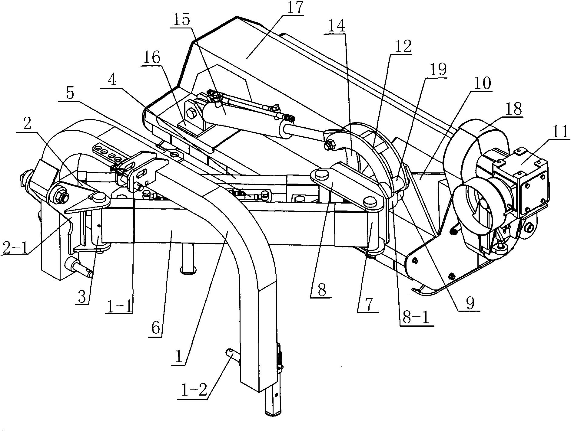
    Figure 1
  • Figure 2
    Figure 2
  • Figure 3
    Figure 3
Patent Text Reader

Abstract

The invention relates to an oscillation device for a brush breaker, which comprises a machine body, a deflection mechanism, an oscillating mechanism and a suspension rack. The oscillating mechanism is a four-link mechanism formed by a left oscillating arm and a right oscillating arm which are hinged on two sides of a front rocker and a rear rocker; two ends of the an oscillating oil / gas cylinder are hinged on the inner sides of the left oscillating arm and the right oscillating arm respectively; one end of the suspension rack is connected with the front rocker; the deflection mechanism comprises a deflection oil / gas cylinder, a deflection connecting rod and a deflection shaft; the deflection shaft which is fixed on the side part of the machine body in an offset mode is rotatably arranged on the rear rocker; the deflection connecting rod hinged on the rear rocker is connected with one end of the deflection oil / gas cylinder; and the other end of the deflection oil / gas cylinder is hinged on the machine body which is reverse to one side of the rear rocker. Under the condition that a tractor is fixed by three-point linkage and in the operation process, the oscillation device can conveniently change and increase the working width of the brush breaker, and the brush breaker can perform cut operation in a deflection tilting mode. The operation is flexible and convenient, the operation efficiency of the brush breaker is greatly improved and different operation requirements can be met.
Need to check novelty before this filing date? Find Prior Art

Description

technical field

[0001] The invention relates to a swing device of a brush cutter, which belongs to the technical field of brush cutters of agricultural and forestry machinery. Background technique

[0002] The brush cutter driven by the output power of the tractor is mainly composed of a hood, a gearbox, a transmission mechanism, and a cutter shaft assembly. The output power of the tractor drives the cutter shaft to rotate through the gearbox and the transmission mechanism, and is used for cutting shrubs and mowing grass. At present, the brush cutters driven by power are all connected with the tractor through the rear three-point suspension. Since the upper and lower suspension positions on the brush cutter are fixed structures, the working width position of the brush cutter cannot be adjusted during operation, so the working width position of the brush cutter cannot be adjusted horizontally relative to the suspension position of the tractor, not only the brush cutter works ...

Examples

Embodiment Construction

[0011] See Figure 1~3 As shown, the swing device of the brush cutter of the present invention includes a body 17, a deflection mechanism, a swing mechanism and a suspension frame 1, a transmission box and a belt chain transmission mechanism are installed on one side of the body 17, and the power output shaft of the tractor is connected to the The transmission box 11 is connected to transmit the power to the transmission box 11 on the brush cutter, and the knife shaft installed on the body 17 is driven to rotate through the chain-type transmission mechanism 18, so that the knife shaft drives the cutter to rotate to cut shrubs or mow grass Wait for homework.

[0012] See figure 1 , 3 As shown, the swing mechanism of the present invention is a four-bar linkage mechanism composed of the left swing arm 4 and the right swing arm 6 hinged on both sides of the front swing frame 2 and the rear swing frame 8, and the front swing frame 2 and the rear swing frame 8 respectively pass th...