Hermetically enclosed refrigerant compressor

A technology of compressors and refrigerants, applied in mechanical equipment, machines/engines, liquid variable displacement machines, etc.

Active Publication Date: 2010-01-20
丹佛斯家用压缩机有限责任公司
View PDF7 Cites 1 Cited by
  • Summary
  • Abstract
  • Description
  • Claims
  • Application Information

AI Technical Summary

Problems solved by technology

Given the circumstances, specific work is required for production, which incurs a corresponding cost

Method used


Image

  • Hermetically enclosed refrigerant compressor
  • Hermetically enclosed refrigerant compressor
  • Hermetically enclosed refrigerant compressor

Examples


Embodiment Construction

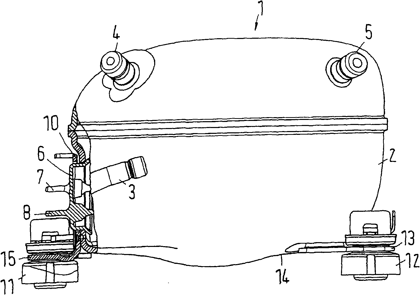
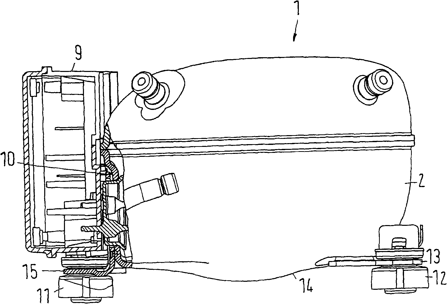
[0028] figure 1 A hermetically sealed refrigerant compressor 1 is shown with a housing 2 in the form of a closed shell. Several connectors 3, 4, 5 protrude from the casing 2, through which refrigerant can be supplied and discharged.

[0029] In known manner, a compressor arrangement is arranged inside the casing 2, said compressor arrangement comprising at least one cylinder with a piston reciprocating inside the cylinder. The piston is driven by an electric motor. The electric motor is supplied with electrical power from the outside, ie through electrical lead-throughs 6 in the form of glass lead-throughs, for example the lead-throughs available on the market under the name "Fusite".

[0030] The electrical lead bushing 6 comprises several electrical contacts 7, 8, figure 2 An electronic unit 9, shown schematically in , can be connected to said electrical contacts. An electronic unit can include several components such as thermostats, frequency converters, fuses, etc.

...


PUM


Abstract

The invention relates to a hermetically enclosed refrigerant compressor with a housing comprising an electrical feed-through, a connection plate (10) arranged outside the housing in the area of the electrical feed-through, and a base plate (15) supporting the bottom of the housing in the gravity direction. The invention attempts to obtain low manufacturing cost. For this purpose, the connection plate (10) and the base plate (15) are made together as one part (16).

Description

[0001] technical field [0002] The invention relates to a hermetically sealed refrigerant compressor with a casing, comprising an electric feed-through, a connecting plate arranged outside the casing in the area of ​​the feed-through, and a base plate supporting the bottom of the casing in the direction of gravity. Background technique [0003] Such a refrigerant compressor is known from EP 0793068A1. Here, the housing is formed as a closed shell comprising connectors for connection to a refrigeration system provided by a compressor. The electrical lead-throughs are designed as glass lead-throughs under the trade name "Fusite". The connection board carries the electronic unit with several components for the electrical control of the electric motor inside the housing. The motor is powered through electrical lead bushings. The substrate is fixed to the bottom of the case. It includes holes through which rubber feet are fixed to the base plate, said rubber feet supporting th...

Claims


Application Information

Patent Timeline
Patent Type & Authority Applications(China)
IPC IPC(8): F04B39/00
CPCF04B39/121
Inventor 安德斯·J·马德森奥拉夫·沃姆德克·霍马思比约恩·兰道
Owner 丹佛斯家用压缩机有限责任公司
Why Eureka
Try Eureka