Bevel ratchet wheel compensating device

A compensating device, bevel ratchet technology, applied in the direction of overhead lines, etc., can solve the problems of inflexible rotation of the ratchet, small tension resistance of the compensation rope, and small compensation distance, so as to achieve reliable comprehensive braking performance and improve safety margins. degree, the effect of increasing the service life

Active Publication Date: 2010-06-02
CHINA RAILWAY HIGH SPEED ELECTRIFICATION EQUIP CORP LTD
View PDF0 Cites 9 Cited by
  • Summary
  • Abstract
  • Description
  • Claims
  • Application Information

AI Technical Summary

Problems solved by technology

However, due to the small compensation distance of the existing ratchet compensation device, the rated working tension is small (the maximum compensation tension of the line is 15kN); the compensation rope has a small tension resistance, the support rigidity is insufficient, and the compensation rope is affected by deviation and friction during work. The service life and transmission effect of the ratchet; the ratchet bracket is made of open hook mouth and welding, which cannot guarantee the requirements of parallelism and verticality, and it is easy to cause the ratchet to be deflected, and the consistency is poor, so it is difficult to interchange; the ratchet bearing cover If the gap between the plate and the side plate of the frame is too small, it is prone to clamping, making the rotation of the ratchet inflexible and affecting the compensation effect
So far, there is no ratchet compensation device that can satisfy the large tension compensation of 37kN or more in the catenary of high-speed electrified railways

Method used


Image

  • Bevel ratchet wheel compensating device
  • Bevel ratchet wheel compensating device
  • Bevel ratchet wheel compensating device

Examples


Embodiment Construction

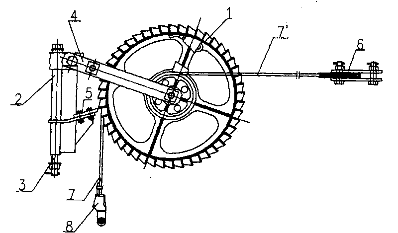
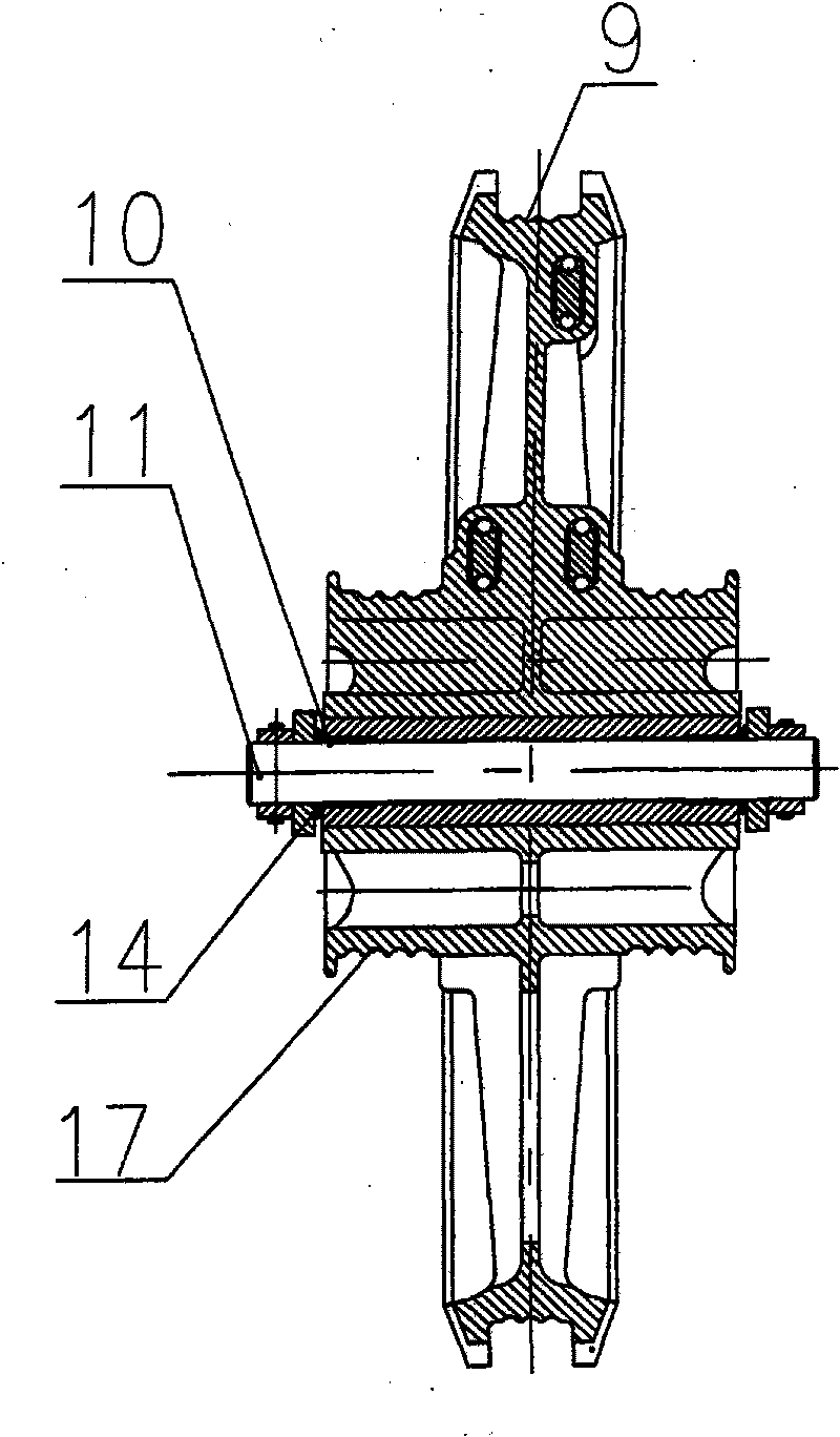
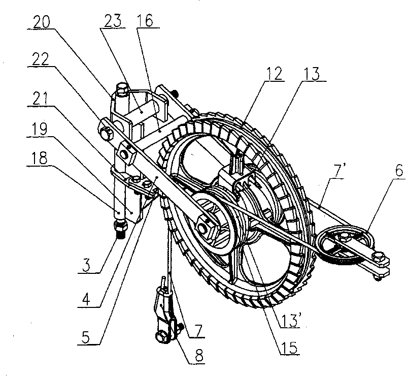
[0024] combined with figure 1 , 2 , 3, 4, 5, 6 describe an embodiment of the present invention.

[0025] A bevel tooth ratchet compensating device, comprising a ratchet body 1, a ratchet brake frame 2, a long bolt pin 3, a ratchet frame connecting lever 4, a brake clamp plate 5, a balance wheel 6, a steel wire rope I7, a steel wire rope II7' and double ear wedge wires Clip 8. The ratchet body 1 is installed on the ratchet shaft 11 through a pair of flanging copper-based self-lubricating sliding bearings 10, and the flanging is located on the outside. The two ends of the ratchet shaft 11 are fixed on the front end of the ratchet frame connecting plate 4, and the two ends of the ratchet shaft 11 are equipped with end face self-lubricating bearings 14, and the end face self-lubricating bearings 14 are located between the ratchet frame connecting plate 4 and the self-lubricating sliding bearing 10 , when the ratchet body deviates so that the flanging of the self-lubricating sli...


PUM


Abstract

The invention provides a bevel ratchet wheel compensating device, comprising a ratchet wheel body (1), a ratchet wheel brake frame (2), a long bolt pin (3), a ratchet wheel framework connecting plate (4), a brake pallet (5), a balance wheel (6), a steel wire rope I (7), a steel wire rope II (7') and a cable clamp (8), wherein two rows of symmetrical bevel gears are arranged on the excircle of a bull wheel (12) of the ratchet wheel body (1), the bevel gear is composed of straight teeth (24) and side teeth (25), the straight teeth (24) are arranged at two sides of the circumference surface of the bull wheel (12), and side teeth (25) are arranged at the side wall of the bull wheel (12); and the front end of the brake pallet (5) is provided with a U-shaped brake port (26) of which the width is consistent with the spacing of the bottom parts of the two side teeth (25). In the invention, the ratchet adopts a bevel structure formed by the straight teeth and the side teeth; by optimizing the structure design, the manufacture technology is simplified, the safe use performance is improved so as to lead the working tension to reach 38.85kN and compensation distance to reach 800m, thus not only satisfying the requirements on high tension and large compensation distance for a high-speed electrified railway contact line, but also having convenient installation and maintenance.

Description

technical field [0001] The invention relates to a bevel gear ratchet compensation device, which belongs to the technical field of high-speed electrified railway catenary component manufacturing. Background technique [0002] The ratchet compensating device is mainly used to compensate and adjust the tension of the cable at the anchorage of the electrified railway catenary and the flexible suspension of urban rail transit. With the development of high-speed electrified railways, the speed of passenger dedicated lines continues to increase, and the requirements for the tension of catenary are relatively high. The compensation tension of the line has been increased to 37kN, and may even be as high as 50kN, so the comprehensive performance of the ratchet compensation device must meet the requirements of large tension compensation. However, due to the small compensation distance of the existing ratchet compensation device, the rated working tension is small (the maximum compensa...

Claims


Application Information

Patent Timeline
Patent Type & Authority Applications(China)
IPC IPC(8): B60M1/26
CPCB60M1/26
Inventor 余福鼎李增勤龚建刚杨小林王红喜张旭峰杜敏陈永瑞赵金凤李昱王永义王展翔
Owner CHINA RAILWAY HIGH SPEED ELECTRIFICATION EQUIP CORP LTD
Why Eureka
Try Eureka