Sightseeing elevator cage

A sightseeing elevator and car technology, applied in the field of elevator cars, can solve the problems of failing to effectively reduce the weight of the car, increase the weight of the car, and offset the center of gravity of the car, so as to reduce the weight of the sightseeing side and improve the installation quality. , the effect of simple and convenient installation

A sightseeing elevator and car technology, applied in the field of elevator cars, can solve the problems of failing to effectively reduce the weight of the car, increase the weight of the car, and offset the center of gravity of the car, so as to reduce the weight of the sightseeing side and improve the installation quality. , the effect of simple and convenient installation

CN101717031AInactive Publication Date: 2010-06-02HITACHI ELEVATOR CHENGDU

Image

  • Sightseeing elevator cage
  • Sightseeing elevator cage
  • Sightseeing elevator cage

Examples


Embodiment Construction

[0016] A sightseeing elevator car of the present invention will be described in detail below in conjunction with the accompanying drawings and specific embodiments.

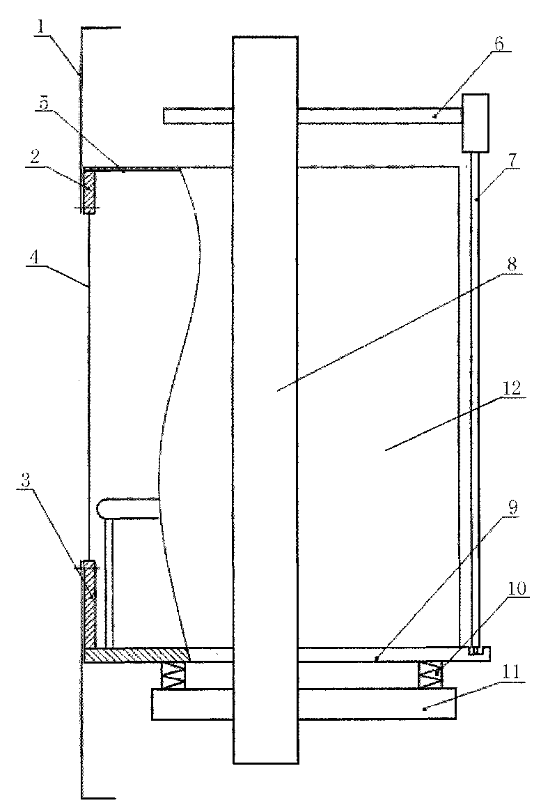
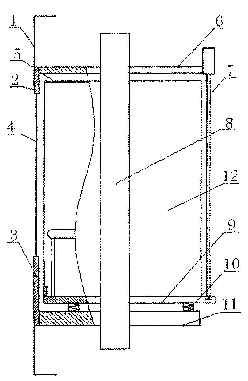
[0017] A sightseeing elevator car, such as figure 2 It includes a car 12 and a car frame, the car is installed on the car frame 11 of the car frame, an elastic weighing device 10 is arranged between the car 12 and the car frame 11, and the outer cover 1 is installed on the rear wall of the car. on the shelf. The car frame includes a car bottom frame 11 , a column 8 and a mounting frame 6 , and the car bottom frame 11 and the mounting frame 6 are rigidly connected through the column 8 . The car door system 7 is installed on the mounting frame 6; the car roof 5 is installed on the side wall plate of the car 12, and the side wall plate is installed on the upper car bottom 9, and the upper car bottom 9 is connected to the car bottom frame through the elastic weighing device 10. 11 connection; the car top 5, the si...


PUM


Abstract

A sightseeing elevator cage comprises a cage and a frame, wherein the cage is arranged on the bottom frame of the frame, an elastic weighing device is arranged between the cage and the bottom frame, and an outer cover is arranged on the frame at the rear wall of the cage; the frame comprises the bottom frame, an upright post and a mounting frame, wherein the bottom frame and the mounting frame are rigidly connected through the upright post; the outer cover is fixed on the mounting frame and the bottom frame; and the outer cover is connected with the mounting frame and the bottom frame through connecting pieces. Compared with the prior art, the sightseeing elevator cage has the advantages of simple and convenient mounting, field mounting quality improvement, high mounting strength, good stability, capability of meeting the requirements on installation of the complex outer cover, reduction in weight of the sightseeing side of the cage, capability of balancing the compression amount of weighing rubber, weighing error reduction and good weighing effect.

Description

technical field [0001] The invention relates to the field of elevator cars, in particular to a sightseeing elevator car. Background technique [0002] At present, the structure of the car of the sightseeing elevator with double car bottom structure and weighing rubber is as follows: figure 1 As shown, the exterior panel (cover) 1 is connected with the upper end 2 of the car rear wall and the lower end 3 of the car rear wall, the upper end 2 of the car rear wall is connected with the car top 5, and the lower end 3 of the car rear wall is installed on the upper car bottom 9 Above, the upper car bottom 9 and the car bottom frame 11 are connected by anti-vibration rubber 10, and the car bottom frame 11, the column 8 and the mounting frame 6 are rigidly connected to form a car frame. The car door system 7 is installed on the mounting frame 6, and the car 12 and the outer panel 1 are movable relative to the car frame. This connection method is relatively complicated. The exterio...

Claims


Application Information

Patent Timeline
02 Jun 2010
Publication
CN101717031A
IPC
B66B11/02
Inventors
刘清鲁; 许秀雄