Filter panel laminates and diaphragm filter panel

A filter plate and membrane technology, applied in the direction of filtration and separation, chemical instruments and methods, separation methods, etc., can solve the problems of poor filtration effect, filter stoppage, etc., and achieve the effect of avoiding inadvertent tearing

Active Publication Date: 2012-12-26
JVK FILTRATION SYST
View PDF1 Cites 2 Cited by
  • Summary
  • Abstract
  • Description
  • Claims
  • Application Information

AI Technical Summary

Problems solved by technology

Such tearing of the filter cloth and / or membrane leads to a poorer filtration effect and, in the worst case, to a longer downtime of the filter as repair measures have to be taken

Method used


Image

  • Filter panel laminates and diaphragm filter panel
  • Filter panel laminates and diaphragm filter panel
  • Filter panel laminates and diaphragm filter panel

Examples


Embodiment Construction

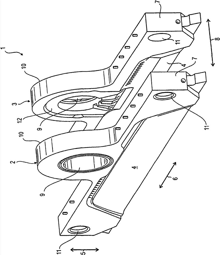
[0068] Such as figure 1 As shown, the filter plate pack 1 includes a membrane filter plate 2 and a cavity filter plate 3 as components of a membrane filter press (not shown in the figure). Each filter plate 2, 3 has an inner plate body and a filter plate surface, namely the filter surfaces 4 on both sides. The filter surface 4 is surrounded on the edge side both in the vertical direction 5 and in the horizontal direction 6 by a filter plate edge, ie a sealing edge 7 , which is thickened relative to the filter surface 4 . In other words, the sealing edge 7 surrounds the filter surface 4 in the vertical direction 5 and in the horizontal direction 6 . exist figure 1 Only the upper parts of the two filter plates 2, 3 are shown in the figure. Both the sealing edge 7 and the filter surface 4 are conceived as extending downward in the vertical direction 5 . The sealing edge 7 protrudes clearly on both sides relative to the filter surface 4 in the installation direction 8 of the f...


PUM


Abstract

A filter panel contains a sludge inlet, a distributor ring which is arranged at the sludge inlet and has at least one inlet channel, and a support ring assigned to the distributor ring. A protective lip is mounted on the support ring and rests on the distributor ring in its closed position and partly covers the inlet channel.

Description

technical field [0001] The invention relates to a filter plate for a filter press. These filter presses all consist of a filter plate stack consisting of several filter plates. The filter plate stack itself consists of a plurality of filter plates arranged next to each other in pairs, which partially abut one another and form a filter chamber between them. For this purpose, the filter plates each have a central filter surface and a sealing edge which is thickened in cross section and frames the central filter surface. The individual filter plates bear against one another with their thickened sealing edges relative to the central filter surface, so that a gap is left between the filter surfaces of adjacent filter plates. This gap between two adjacent filter plates is used as a filter chamber. Those filter plates can be separated from each other in the filter press and can be moved closer to each other. This mobility is used to open or close the filter cavity. Background t...

Claims


Application Information

Patent Timeline
Patent Type & Authority Patents(China)
IPC IPC(8): B01D25/21B01D25/30
CPCB01D25/164B01D25/21B01D25/176B01D25/285
Inventor M·P·赫尔曼
Owner JVK FILTRATION SYST
Why Eureka
Try Eureka