Novel escape door lock

A door lock and a new type of technology, applied in the field of locks, can solve the problems of difficult promotion, poor safety exit lock evacuation channel, safety exit control door lock has not been fully promoted and applied, etc., to achieve strong reliability and ensure anti-theft safety. Effect

Inactive Publication Date: 2012-03-07
马刘陈
View PDF0 Cites 0 Cited by
  • Summary
  • Abstract
  • Description
  • Claims
  • Application Information

AI Technical Summary

Problems solved by technology

[0002] For a long time, safety exit management has been troubled by the contradiction between public security management and fire protection management. From the perspective of security prevention, the stronger the exit lock, the better. From the perspective of accident escape, the smoother the safety passage, the more effective. Locking the safety door is a taboo for escape in an accident; according to statistics, most of the fire accidents that caused more casualties were caused by the locking of the safety exit or the poor evacuation passage; therefore, the control of the safety exit The problem has been widely concerned by firefighting technicians and managers of densely populated places, and the research on safety exit management has never stopped
[0003] In recent years, domestic and foreign countries have successively developed some safety exit control door locks. Although these products have solved the reliability of door opening, they have relatively large defects in the locking function of the door, so they are not used by managers in densely populated places. Optimistic, it is very difficult to promote, and the fundamental reason why the current safety exit control door locks have not been fully promoted and applied is this

Method used


Image

  • Novel escape door lock
  • Novel escape door lock
  • Novel escape door lock

Examples


Embodiment Construction

[0019] Below in conjunction with accompanying drawing and specific embodiment the present invention is described in further detail:

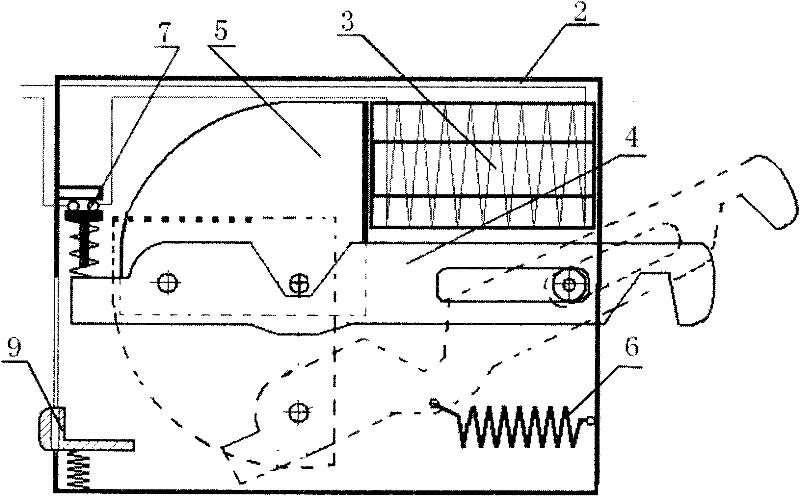
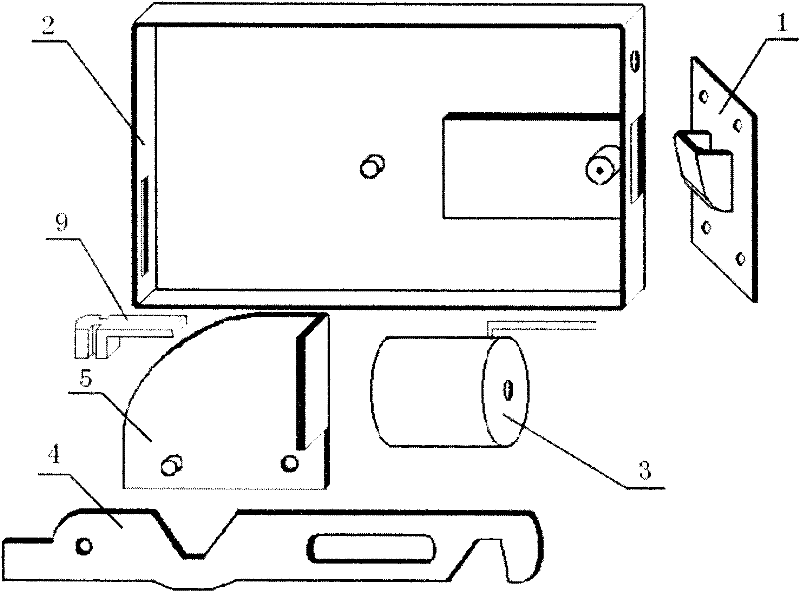
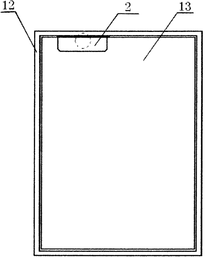
[0020] Such as figure 1 , figure 2 , image 3 , Figure 4 with Figure 5 As shown, a novel escape door lock includes a lock housing 2, a shell cover, a lock head slot 1, a lock head, an electromagnet 3, a touch switch 7, a lock machine 5, a shift block 9, a shift block return spring and Lock return spring 6;

[0021] The lock groove 1 includes a fixing plate and a hook groove body arranged on the fixing plate;

[0022] The lock head is a strip 4, a door hook is provided on one side of the outer end of the strip 4, and a strip-shaped sliding hole is arranged on the strip 4, and the strip-shaped sliding hole is close to the bottom of the strip 4. door hook setting;

[0023] The lock 5 includes a curved plate and an electromagnet suction plate arranged at one end of the curved plate, the curved plate and the electromagnet suction plate are ...


PUM


Abstract

The invention provides a novel escape door lock, which comprises a lock shell, a shell cover, a locking head groove, a locking head, an electromagnet, a touch switch, a locking machine, a shifting block, a shifting block return spring and a locking head return spring. The locking head groove comprises a fixing plate and a slot body; the locking head is a ribbon board which comprises a door hook and a strip slide opening; the locking machine comprises a curved plate and an electromagnet suction plate; the shifting block comprises a clamping groove body and a push plate; the touch switch corresponds to the ribbon board and is connected with the electromagnet; the inner wall of the lock shell is provided with a sliding post which is near the outlet of the locking head; the ribbon board is sleeved on the sliding post through the strip slide opening; the door hook passes through the outlet of the locking head of the lock shell; the clamping groove body is arranged on a pull groove port of the lock shell; the shifting block return spring is connected between the lock shell and the push plate; the push plate corresponds to the ribbon board; the locking head return spring is connected between the lock shell and the ribbon board; and the electromagnet suction plate corresponds to the electromagnet. The door lock has the advantages of convenient use, firm locking, convenient and fast door opening, safety and reliability.

Description

technical field [0001] The invention relates to a lockset, in particular to a novel escape door lock for fire protection. Background technique [0002] For a long time, safety exit management has been troubled by the contradiction between public security management and fire protection management. From the perspective of security prevention, the stronger the exit lock, the better. From the perspective of accident escape, the smoother the safety passage, the more effective. Locking the safety door is a taboo for escape in an accident; according to statistics, most of the fire accidents that caused more casualties were caused by the locking of the safety exit or the poor evacuation passage; therefore, the control of the safety exit The problem has always been widely concerned by firefighting technicians and managers of densely populated places, and the research on safety exit management has never stopped. [0003] In recent years, domestic and foreign countries have successive...

Claims


Application Information

Patent Timeline
Patent Type & Authority Patents(China)
IPC IPC(8): E05B65/10E05B47/02E05B17/22
Inventor 马刘陈马圆棓王素梅李尚永高新志杨春波
Owner 马刘陈
Why Eureka
Try Eureka