

Bearing gear unit for paper maker or carton machine
A technology of transmission unit and bearing, which is applied in paper machine, paper making, textile and paper making, etc. It can solve the problems of complex and expensive structure, complex removal of gears, etc., and achieve the effect of reducing the number of pipelines, reducing maintenance intensity, and easy loading and unloading
- Summary
- Abstract
- Description
- Claims
- Application Information
AI Technical Summary
Problems solved by technology
Method used
Image

Examples
Embodiment Construction
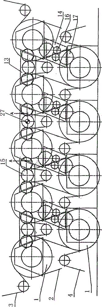
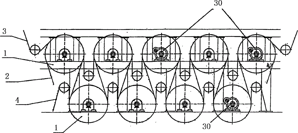
[0032] figure 1 A drying group of dryer components in the prior art is shown. Here, the paper web 2 is guided along a tortuous path past the drying cylinder 1 , which is pressurized from the inside with steam so that the cylinder shell is heated. In this process, the wet paper web 2 wrapped around the drying cylinder 1 is dried as quickly as possible, in which condensation water forms, which is drained off through holes drilled in the journal. The drying cylinder 1 is arranged in two layers, and the bottom row can also be replaced by suction rollers.
[0033] The paper web 2 is pressed against the surface of the drying cylinder by the wires 3, 4 to achieve the best possible contact and thus the best drying efficiency.
[0034] exist figure 1 In order to drive all the drying cylinders 1 and connect them to each other, a horizontal gearbox 13 or a vertical gearbox 14 is used. These gearboxes 13, 14 house a corresponding number of so-called intermediate gears 15, 16, 17 wit...
PUM
 Abstract
Description
Claims
Application Information