Overwater-installed submersible water impeller

A submersible flowmaker and flowmaker technology, applied in the direction of sustainable biological treatment, aerobic process treatment, anaerobic digestion treatment, etc., can solve the problems of high installation and maintenance costs, high equipment failure rate, long time period, etc. Achieve stable work, improve reliability, and improve performance

Active Publication Date: 2010-12-08
ASIA PACIFIC WATER TREATMENT TIANCHANG
View PDF5 Cites 7 Cited by
  • Summary
  • Abstract
  • Description
  • Claims
  • Application Information

AI Technical Summary

Problems solved by technology

[0003]The present invention provides a submersible thruster installed on water, which not only does not need to release water during maintenance and installation, but also does not need to go down to the bottom of the pool, and directly passes through the lifting device on the water It is very convenient and quick to install and maintain with the suspended truss coupling structure, avoiding the need to drain the pool water and the need for personnel to go down to the bottom of the pool for operation during the installation and maintenance of the main body of the flow booster, which fundamentally solves the inconvenience of installation, Difficult maintenance, long time period, high installation and maintenance costs, many potential safety hazards, and high equipment failure rate, etc., and can realize the functions of automatic positioning, automatic fixing and automatic clamping of the main body of the flow booster, and automatic lifting after lifting. Disengagement effectively improves the reliability of the structure, effectively resists impact loads, absorbs vibrations, makes the equipment work smoothly, improves performance, and reduces failures. At the same time, the suspended truss structure adopted in the present invention can effectively improve the reliability of the structure. , reducing the complexity of the equipment and the difficulty of on-site assembly, stable work, improved performance, and reduced failures

Method used


Image

  • Overwater-installed submersible water impeller
  • Overwater-installed submersible water impeller
  • Overwater-installed submersible water impeller

Examples


Embodiment Construction

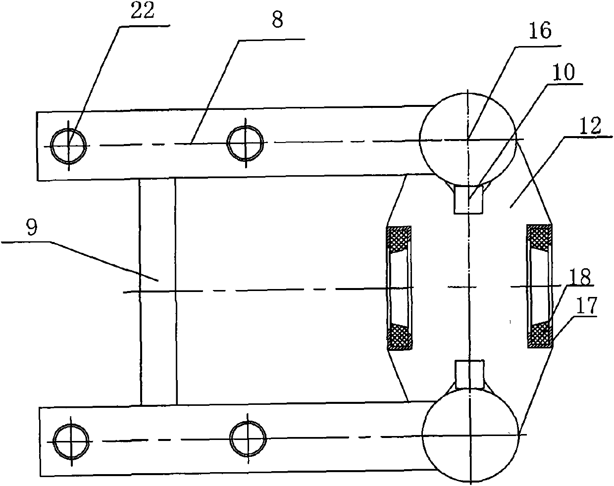
[0026] exist figure 1 Among them, the present invention is a submersible thruster installed on water, which includes a thruster main body 1, a lifting device 2 and an installation and fixing foundation 3 on the pool top, an impeller 4 is arranged on the thruster main body 1, and the lifting device 2 is fixed On the installation and fixing foundation 3 on the top of the pool, a suspended truss structure is provided between the main body of the flow booster 1 and the fixed installation foundation 3 on the top of the pool. 5 is fixedly connected with the fixed installation foundation 3 on the top of the pool, and is connected with the horizontal truss 5 at the top of the guide rail type vertical truss 6, and a coupling device 7 is provided on the surface of the bottom plate 12 at the bottom, and the main body of the flow booster 1 is set on the coupling device 7 for Automatically coupled in place and automatically positioned and clamped, the lifting device 2 can drive the flow bo...


PUM


Abstract

The invention discloses an over-installed submersible water impeller. A suspended-type truss structure is arranged between a water impeller main body (1) and a fixed installed base (3) at a pool top and comprises a horizontal truss (5) and a guide-rail type vertical truss (6), wherein the horizontal truss (5) is fixedly connected with the fixed installed base (3) at the pool top, the top end of the guide-rail type vertical truss (6) is connected with the horizontal truss (5), a coupling device (7) is arranged on the surface of a bottom plate (12) at the bottom end, the water impeller main body (1) is arranged on the coupling device (7) and used for carrying out automatic coupling in-position and automatic positioning and clamping, and a lifting device (2) can drive the water impeller main body (1) to move up and down along the guide-rail type vertical truss (6).

Description

technical field [0001] The invention relates to a submersible thruster installed on water. Background technique [0002] In the sewage treatment industry, submersible flowmakers are widely used in anaerobic pools, anoxic pools and aeration tanks. Generally, the depth of the pool is about 5 meters. It is one of the key core equipment for sewage treatment to promote the flow of water medium, increase the flow velocity at the bottom of the pool, prevent sludge settlement, and improve the efficiency of sewage treatment. Due to the high technical content of this equipment, it has a great influence on the discharge of sewage treatment standards, the import rate is relatively large, and the market consumption is relatively large. Conventional submersible flowmaker equipment includes submersible flowmaker host, lifting device, underwater guide rail and underwater placement seat (the placement seat is generally a flat or circular tube structure), and the underwater placement seat is...

Claims


Application Information

Patent Timeline
Patent Type & Authority Applications(China)
IPC IPC(8): C02F3/02C02F3/28
CPCY02W10/10
Inventor 梅红霖丁九光李波季飞
Owner ASIA PACIFIC WATER TREATMENT TIANCHANG
Why Eureka
Try Eureka