Connecting device

A connecting device and connecting rod technology, which is applied in the direction of lighting devices, display devices, lighting auxiliary devices, etc., can solve the problems of poor wind resistance, pulling deformation of the aluminum alloy frame of the light box, falling off of the light box and street lamp pole, etc., and achieve wind resistance performance Improve the effect of avoiding deformation

Inactive Publication Date: 2012-09-05
HANGZHOU AOTU LIGHT TECH
View PDF4 Cites 0 Cited by
  • Summary
  • Abstract
  • Description
  • Claims
  • Application Information

AI Technical Summary

Problems solved by technology

[0003] In addition to the above two connection methods, there are other connection methods on the market, but they all use screws or welding to install the light box on the metal sheet or base. A big defect of these connection methods is that the wind resistance is poor
Since the pattern cover of the light box generally has a larger area, when the external wind force is relatively large and acts on the pattern cover of the light box in a vertical direction, a greater pressure will be generated on the light box, so that there will be a certain pressure on the connecting part of the light box. Destructive force, long-term external wind force will cause the aluminum alloy frame of the light box to be pulled and deformed, and even the light box will fall off the wall or street light pole.

Method used


Image

  • Connecting device
  • Connecting device
  • Connecting device

Examples


Embodiment Construction

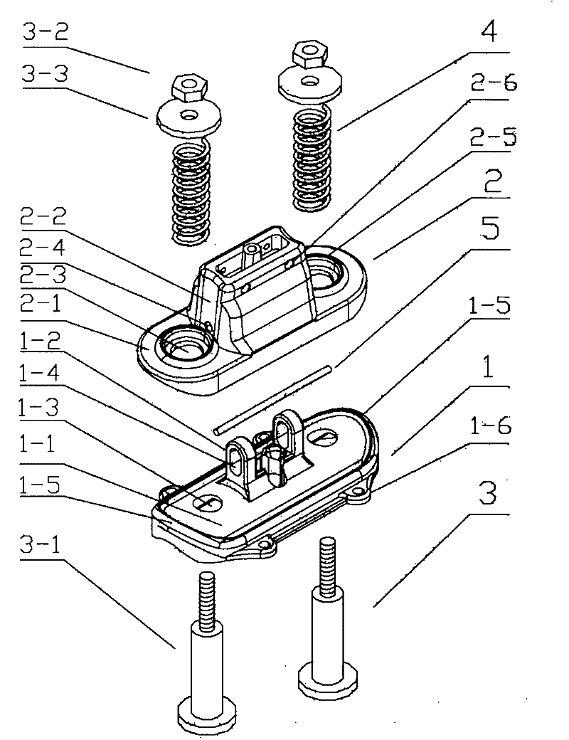
[0014] The specific embodiments of the present invention will be described below in conjunction with the accompanying drawings.

[0015] Such as image 3 , Figure 4 As shown, the connection device provided by the present invention includes a lower base 1, an upper base 2, two connecting rods 3, two compression springs 4, and a pin 5, wherein the lower base 1 includes a lower base plate 1-1 and a protrusion on the lower base plate. Protrusion 1-2, the number of protrusions is 2, the upper base 2 includes an upper bottom plate 2-1 and a convex shell 2-2 on the upper bottom plate, and the protrusion 1-2 is placed in the cavity of the convex shell 2-2; Both ends of the lower base plate 1-1 are provided with two through holes 1-3 for inserting connecting rods, and two ends of the upper base plate 2-1 are also provided with two through holes 2-3 for inserting connecting rods. The connecting rod 3 includes bolts 3-3. 1. Nut 3-2, washer 3-3, the nut 3-2 is threadedly connected with...


PUM


Abstract

The invention provides a connecting device. The connecting device comprises a lower base, an upper base, two connecting rods, two compression springs and a pin, wherein the lower base comprises a lower bottom plate and a bulge on the lower bottom plate; the upper base comprises an upper bottom plate and a convex shell on the upper bottom plate; the bulge is arranged in a cavity of the convex shell; two through holes into which the connecting rods are inserted are formed at the two ends of the lower bottom plate; two through holes into which the connecting rods are inserted are also formed at the two ends of the upper bottom plate; the rod parts of the connecting rods pass through the through holes of the lower bottom plate, the through holes of the upper bottom plate and the compression springs in turn; a pin hole is also formed on the bulge on the lower bottom plate; pin holes are formed on the two sides of the convex shell on the upper bottom plate; the pin passes through the pin hole on one side of the convex shell, the pin hole on the bulge, and the pin hole on the other side of the convex shell in turn; the pin hole on the bulge is strip; and the pin can relatively move in the pin hole on the bulge in the axial direction of the connecting rods. The invention has the advantage that: when outside wind power is high, the wind resistance of a light box which is arranged by the connecting device provided by the invention is improved.

Description

technical field [0001] The invention relates to a connection device for installing a light box or other similar items on a wall or a street light pole. Background technique [0002] At present, a common light box on the market includes a frame and a pattern cover. The frame is mostly made of aluminum alloy, and a luminous body is placed inside, such as a lamp tube, a light bulb or an LED lamp. The pattern appears at night, and the light box is usually installed on the wall or street light pole. Such as figure 1 As shown, when the light box 10 is installed on the wall, a common connection method is to install it through the metal mounting piece 20. The metal mounting piece 20 is provided with a raised portion 21, and the light box is installed on the raised portion of the metal mounting piece 20 by screws. 21. Install the metal mounting sheet 20 on the wall with screws. Such as figure 2 As shown, when installing the light box on the street light pole, a common connection...

Claims


Application Information

Patent Timeline
Patent Type & Authority Patents(China)
IPC IPC(8): F21V21/00G09F13/04
Inventor 周云锋
Owner HANGZHOU AOTU LIGHT TECH
Why Eureka
Try Eureka