Voltage changer and voltage changing system

A transformer and voltage technology, applied in instruments, static indicators, etc., can solve the problems of long duration, transient power consumption, large current, etc., to enhance the current driving capability, avoid short-circuit current, and reduce the layout area. Effect

Active Publication Date: 2011-03-02
ORISE TECH CO LTD
View PDF4 Cites 2 Cited by
  • Summary
  • Abstract
  • Description
  • Claims
  • Application Information

AI Technical Summary

Problems solved by technology

In order to meet a sufficiently large channel width-to-length ratio, the layout area of ​​the existing converter 10 cannot be effectively reduced
[0006] In addition, when the input signal undergoes the aforementioned transition, the large current turned on by the transistor TP1 will also cause a short-circuit current with a large current and a long duration during the competition period, which will affect the characteristics of the existing converter 10, such as transient power consume

Method used


Image

  • Voltage changer and voltage changing system
  • Voltage changer and voltage changing system
  • Voltage changer and voltage changing system

Examples


Embodiment Construction

[0070] In order to make the object, technical solution, and advantages of the present invention clearer, the present invention will be further described in detail below with reference to the accompanying drawings and examples.

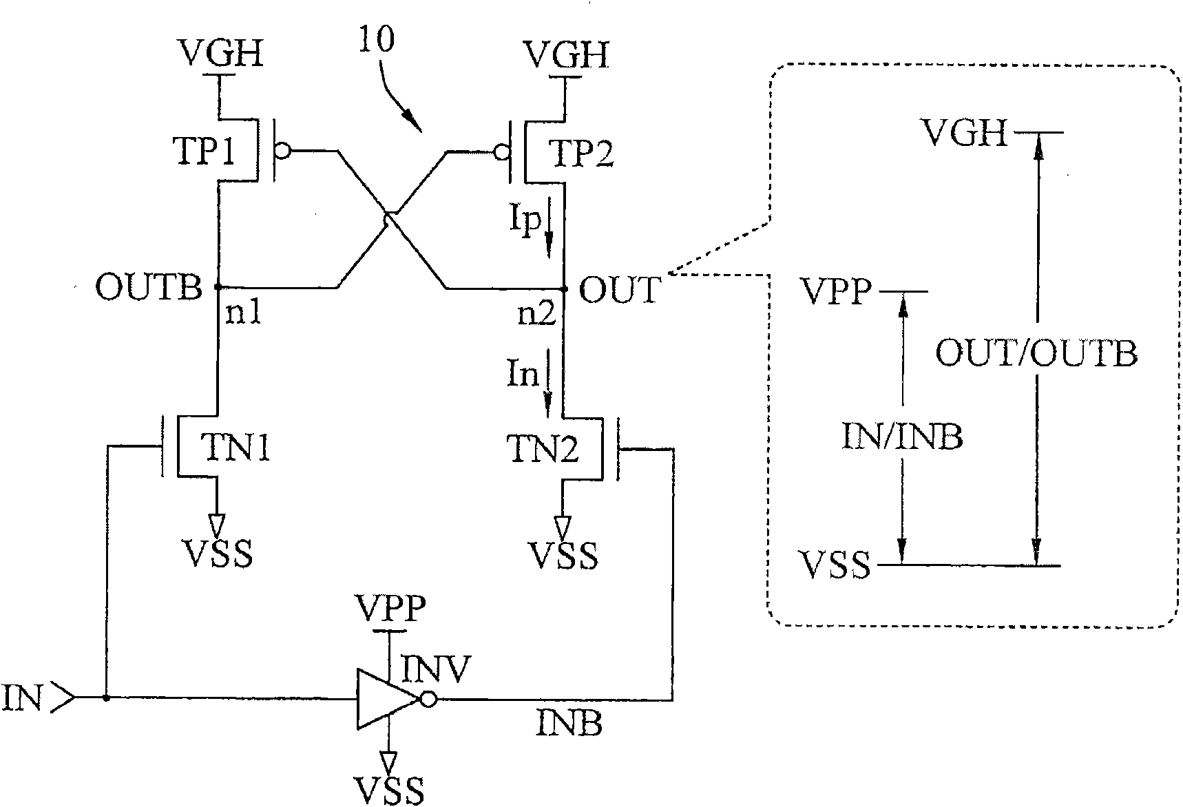
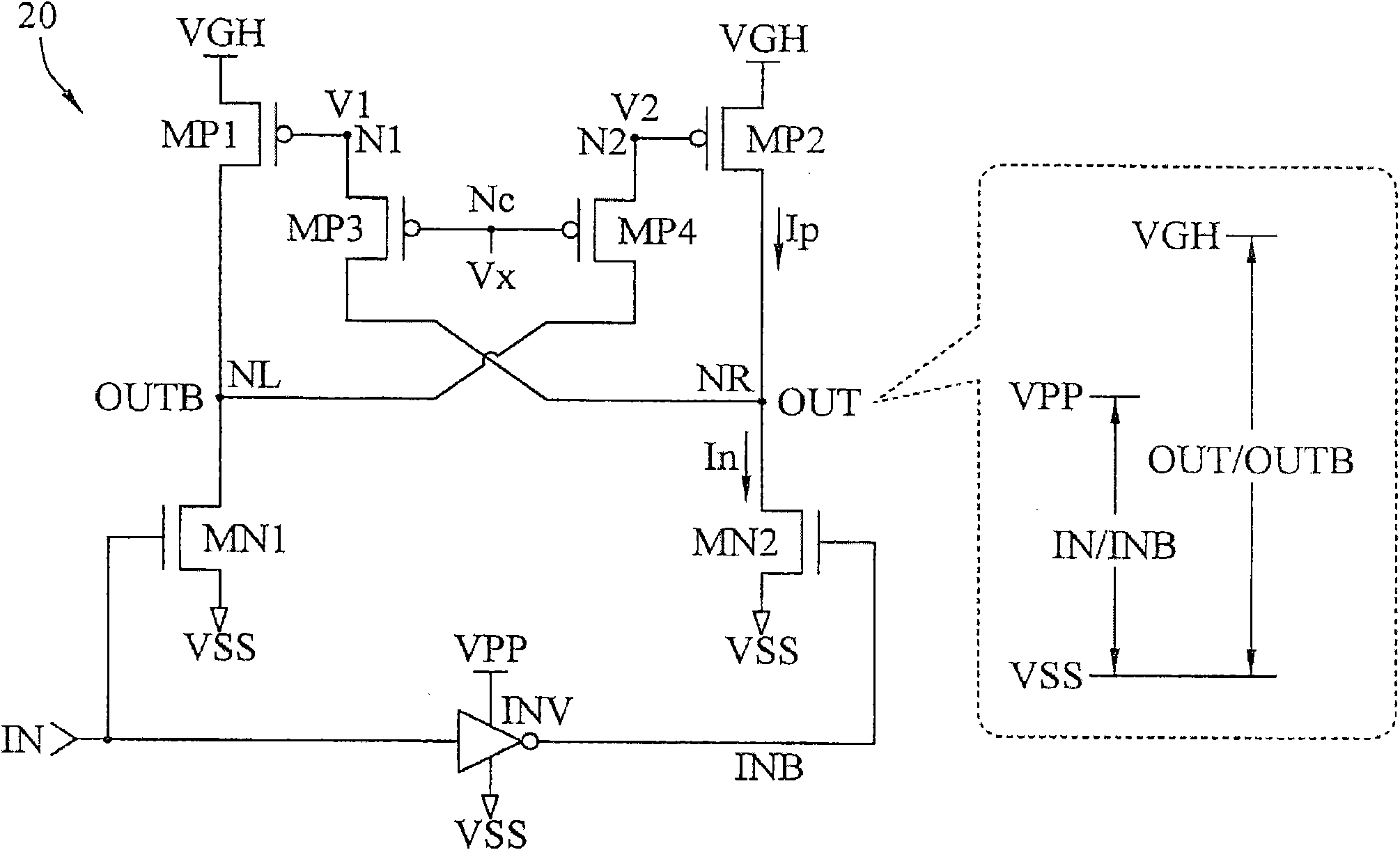
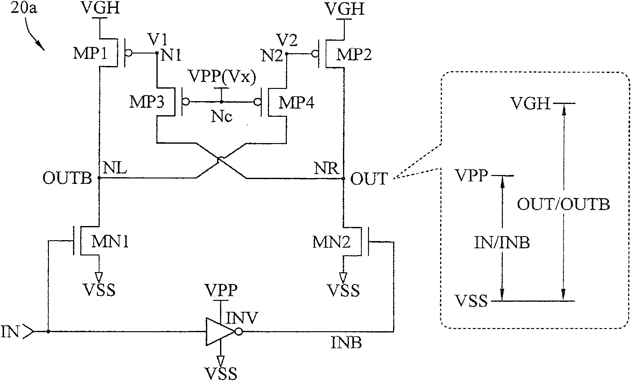
[0071] The present invention provides a voltage converter and a voltage conversion system. The switching circuit in the converter is based on the common voltage received by one of the first connection terminal and the second connection terminal and a bias voltage received by the bias voltage connection terminal. Select one of the third connection terminal and the fourth connection terminal to output a trigger signal, so that the second current circuit coupled to the connection terminal outputting the trigger signal will pull up the voltage of the output terminal that does not output the common voltage to the second voltage; the conduction degree of the second current circuit can be limited through the trigger signal, and there is no need to increase the...


PUM


Abstract

The invention provides a voltage changer and a voltage changing system. A first circuit of the voltage changer outputs a common voltage on one of a first output end and a second output end according to an input signal and a received common voltage; a second current circuit conducts one, which does not receive the common voltage, of a third output end and a fourth output end to a second voltage according to a received triggering signal; and a switch circuit selects one of a third connection end and a fourth connection end to output the triggering signal according to the common voltage received by one of a first connection end and a second connection end and a bias voltage received by a bias voltage connection end so that a second current circuit coupled with the connection end outputting the triggering signal boosts the voltage of the output end which dose not output the common voltage to a second voltage. By using the voltage changer and the voltage changing system, the triggering signal restricts the conduction degree of the second current circuit, and the current drive capability can be enhanced with no need of increasing the distribution area, thereby effectively shortening the distribution area and reducing short-circuit current.

Description

technical field [0001] The invention relates to voltage conversion technology, in particular to a voltage converter and a voltage conversion system. Background technique [0002] The transformer can receive the input signal with a small signal range and convert it into an output signal with a large signal range correspondingly, and is an important component in the interface circuit. For example, in the source driver chip driving the display panel, the signal range of the original control signal in the chip is 0 to 2 volts, but when it is output to the source electrode driving the display panel, the signal range required It may be necessary to expand to 0 to 5 volts. In order to smoothly convert between the two signal ranges, a transformer is needed to convert the 0 to 2 volt input signal into a 0 to 5 volt output signal. [0003] figure 1 It is a structural schematic diagram of an existing converter. Please refer to figure 1 , which shows a conventional transformer 10 ....

Claims


Application Information

Patent Timeline
Patent Type & Authority Applications(China)
IPC IPC(8): G09G3/20
Inventor 郑彦诚黄健群
Owner ORISE TECH CO LTD
Why Eureka
Try Eureka