A contact structure of an off-excitation tap changer

A tap-changer and contact technology, applied in the direction of prior contact arrangement, etc., can solve the problems of inconvenient operation, increased switch shifting torque, affecting the reliability of switch use, etc., and achieve accurate and reliable positioning, reduced deformation, and stable contact. Performance and reliability remain the same

Active Publication Date: 2011-12-14
徐优燕
View PDF5 Cites 4 Cited by
  • Summary
  • Abstract
  • Description
  • Claims
  • Application Information

AI Technical Summary

Problems solved by technology

However, the operating torque of the contact structure mainly depends on the distance between two adjacent static contacts, the diameter of the annular moving contact, the radial pressure of the spring, and the number of moving contacts. Since the spring pressure is generally fixed , when the switching current is large, the number of annular moving contacts is more, and at the same time, the distance between the static contacts will increase correspondingly when the insulation level is high, so that the moving contacts will cut deeper into the static contacts. When shifting gears, these factors not only increase the gear shifting torque of the switch and bring inconvenience to the operation, but also affect the reliability of the switch, especially the switch with high current and multi-phase combination. These factors will make the contact structure App is restricted

Method used


Image

  • A contact structure of an off-excitation tap changer
  • A contact structure of an off-excitation tap changer
  • A contact structure of an off-excitation tap changer

Examples


Embodiment Construction

[0020] Embodiments of the present invention are further described below in conjunction with the accompanying drawings:

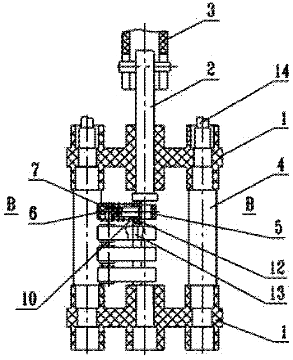
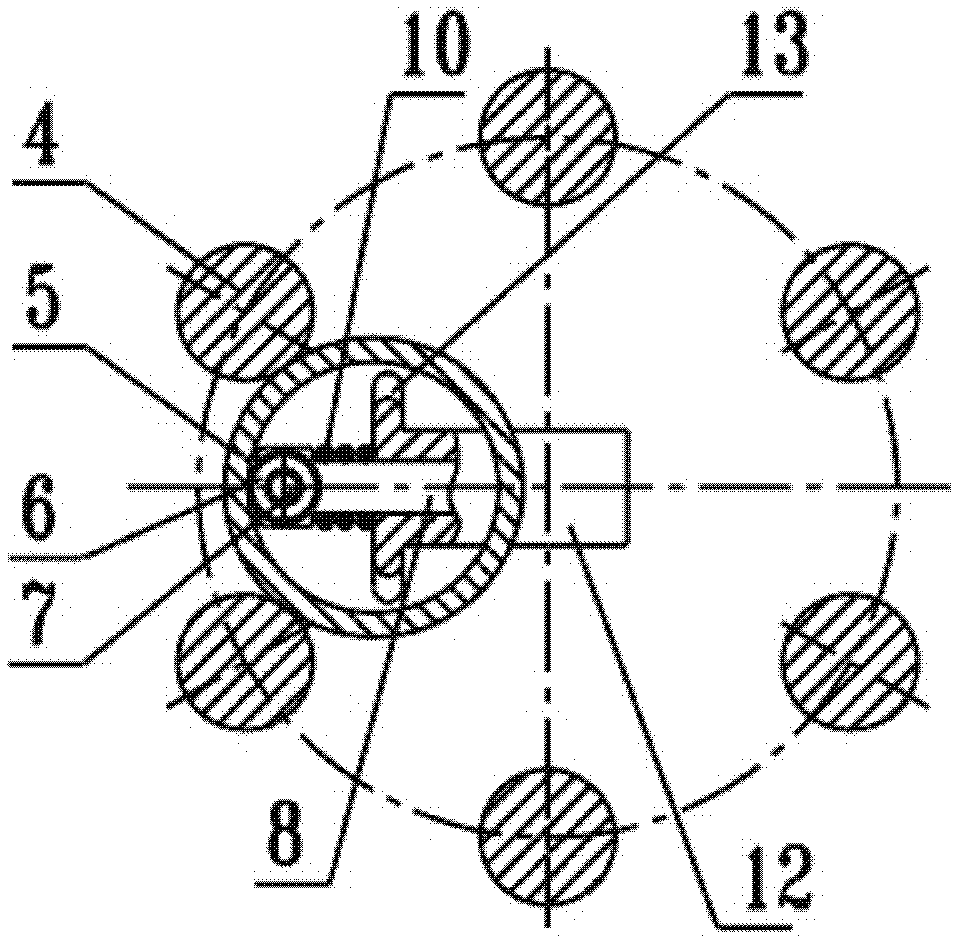
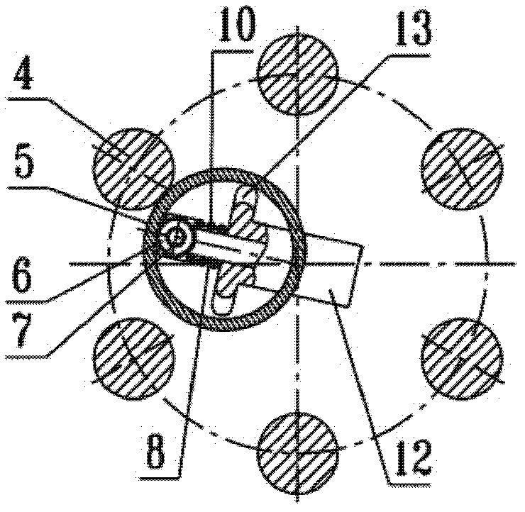
[0021] An example of the present invention is figure 1 , 2 As shown in , 3 and 4, it is a single-phase five-speed non-excitation drum tap-changer, including a switch support 1 arranged up and down, a main shaft 2 is installed between the two switch supports, and the upper end of the main shaft is connected with the switch operating mechanism 3 Connected, the main shaft is equipped with an eccentric support 12, and a columnar fixed contact 4 is arranged at intervals along the circumferential direction between the two switch supports. The upper end of the columnar fixed contact is connected with a lead wire or a terminal 14, and two adjacent columnar There is an annular movable contact 5 across the fixed contacts, which is set on the supporting piece and configured with the radial sliding pin 8 and the spring 10 installed on the supporting piece. The front en...


PUM


Abstract

The invention relates to a contact structure of a non-excitation tapping switch for a transformer. The contactor structure comprises switch supports and a main shaft which are arranged up and down, wherein the main shaft is provided with eccentric supporting pieces; columnar fixed contacts are arranged between the two switch supports at intervals along the circumferential direction; an annular moving contact is bridged between every two adjacent columnar fixed contacts; the annular moving contacts are sleeved on the supporting pieces and are matched with radial slide pins and springs which are arranged on the supporting pieces; each moving contact comprises two or more than two annular moving contacts; and lateral stirring pieces are arranged on both sides of each supporting piece corresponding to the inner holes of the annular moving contacts. The contact structure is characterized in that: the lateral directions of the lateral stirring pieces on one side or both sides are different up and down or staggered, and the lateral stirring pieces are distributed in step or staggered step way. The moving contacts are sectionally stirred in a time division way to effectively reduce the superposition of the maximum rotational torque during the gear shift of the moving contacts and conveniently complete the tapping switch of the switch; the moving contacts are precisely and reliably positioned; and the stable contact performance and reliability of the moving contacts and the fixed contacts are kept unchanged.

Description

technical field [0001] The invention relates to a contact structure of an off-excitation tap changer for a transformer. Background technique [0002] The existing off-excitation tap changer contacts include a fixed contact and a moving contact that bridges between two adjacent fixed contacts. The fixed contact is mostly a columnar fixed contact, and the moving contact is mostly a ring-shaped moving contact. , The annular movable contact is usually arranged in multiples along the axial direction, and the annular movable contact maintains elastic contact with the fixed contact under the radial spring force. When shifting gears, the annular movable contact makes a circumferential displacement under the action of the torque of the main shaft and the supporting member, overcomes the pressure of the spring and runs from one side to the other along the surface of the cylindrical fixed contact to complete the gear shifting process. The ring-shaped moving contact has the characteris...

Claims


Application Information

Patent Timeline
Patent Type & Authority Applications(China)
IPC IPC(8): H01H1/56
Inventor 徐优燕
Owner 徐优燕
Why Eureka
Try Eureka