
Circuit for displaying any Poincare section plane in three-dimensional space by using oscillograph
A technology for displaying circuits and three-dimensional space, applied in digital variable/waveform display, instrument, measuring electric variable, etc., can solve the problem that the oscilloscope cannot display the Poincaré section
- Summary
- Abstract
- Description
- Claims
- Application Information
AI Technical Summary
Problems solved by technology
Method used
Image

Examples
Embodiment 1
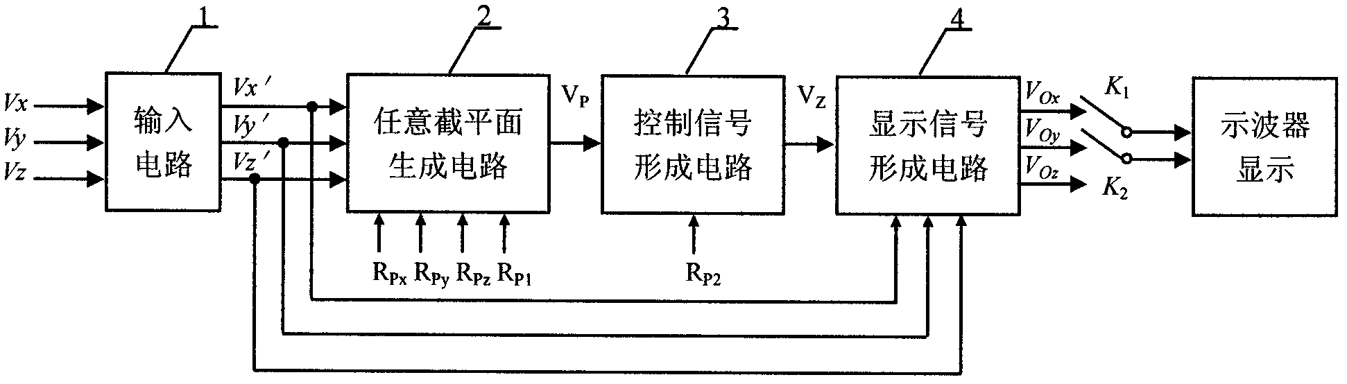
[0023] Example 1: Combining Figure 1-Figure 5 , the present invention a kind of oscilloscope display circuit of arbitrary Poincaré sectional plane in three-dimensional space, it is by input circuit (1), arbitrary sectional plane generating circuit (2), control signal forming circuit (3) and display signal forming circuit (4 ), the input circuit
[0024] (1) connect any sectional plane generating circuit (2), any sectional plane generating circuit (2) connect control signal forming circuit (3), control signal forming circuit (3) connect display signal forming circuit (4), input circuit (1 ) is also connected with the display signal forming circuit (4).
[0025] The present invention also has the following technical characteristics:
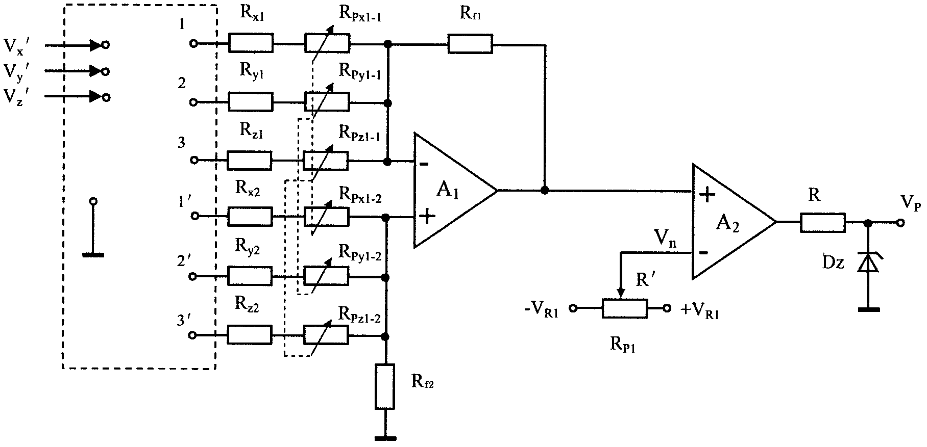
[0026] The arbitrary sectional plane generating circuit (2) includes resistances: R, R x1 , R x2 , R y1 , R y2 , R z1 , R z2 , R f1, R f2 , Potentiometer R P1 , the first double potentiometer (R Px ), the second double potentiometer (R...
Embodiment 2
[0029] Example 2: Combining Figure 1-Figure 11 , each circuit part of the present invention is introduced below:
[0030] 1. Input circuit
[0031] The purpose of the input circuit 1(1) is to realize the measurement of various system signals under test with an oscilloscope. The main function is to transform the impedance and scale up or down the signal as needed. Receive the voltage signal V of the three variables of the system under test x , V y and V z , output the corresponding three voltage signals V x ', V y ' and V z '.
[0032] 2. Arbitrary sectional plane generation circuit
[0033] Arbitrary sectional plane generation circuit 1 (2) is the generation circuit of any Poincaré section ax+by+cz=d (wherein a, b, c and d are arbitrary real values), such as figure 2 and Figure 5 shown. The dotted line frame part of the circuit is used to determine the direction of the input signal; the arbitrary section circuit is composed of an addition and subtraction hybrid ...
Embodiment 3
[0042] Example 3: Binding Figure 2-Figure 4 ,Figure 6- Figure 11 , the arbitrary sectional plane generating circuit (2) of the present invention, such as figure 2 shown. due to R f1 =R f2 =R f , R x1 =R x2 =R x , R y1 =R y2 =R y , R z1 =R z2 =R z , R Px1-1 =R Px1-2 =R Px , R Py1-1 =R Py1-2 =R Py , R Pz1-1 =R Pz1-2 =R Pz , and the 1 and 1' terminals are always connected to V x 'The other is grounded; 2 and 2' are always connected to V y 'The other is grounded; 3 and 3' are always connected to V z ’ Another ground. No matter how to adjust the double potentiometer R Px , R Py or R Pz , both guarantee that the op amp A 1 The resistance of the two input terminals is equal, that is, R f1 / / (R x1 +R Px1-1 ) / / (R y1 +R Py1-1 ) / / (R z1 +R Pz1-1 ) = R f2 / / (R x2 +R Px1-2 ) / / (R y2 +R Py1-2 ) / / (R z2 +R Pz1-2 ) = R f / / (R x1 +R Px ) / / (R y1 +R Py ) / / (R z1 +R Pz ). And because terminals 1, 2, and 3 are located in the operational amplifier (...
PUM
 Abstract
Description
Claims
Application Information