Weft insertion apparatus in jet loom

A weft insertion device, jet loom technology, used in looms, textiles, textiles, and papermaking

Active Publication Date: 2014-03-19
TOYOTA IND CORP
View PDF11 Cites 0 Cited by
  • Summary
  • Abstract
  • Description
  • Claims
  • Application Information

AI Technical Summary

Problems solved by technology

Therefore, the air jet direction line C is more likely to deviate upward from the weft guide channel 14

Method used


Image

  • Weft insertion apparatus in jet loom
  • Weft insertion apparatus in jet loom
  • Weft insertion apparatus in jet loom

Examples


Embodiment Construction

[0037] An embodiment of the present invention will be described with reference to FIGS. 1 to 8 . The overall structure of the weft insertion device including the auxiliary nozzle for weft insertion is the same as that in FIG. 9 .

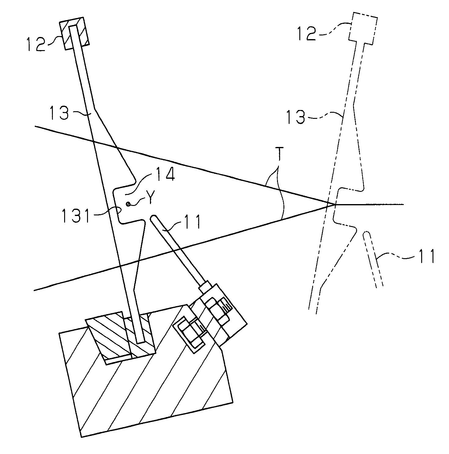
[0038] FIG. 1( a ) is a front view of a part of the auxiliary nozzle 21 for weft insertion and a part of the deformed reed 12 . Fig. 1(b) is a sectional view of Fig. 1(a) taken along line 1b-1b. FIG. 2( a ) is a side view of the tip of the auxiliary nozzle 21 . The tip of the auxiliary nozzle 21 is rounded or arcuate when viewed along the weft insertion direction Lo. Fig. 2(b) is a cross-sectional view of Fig. 2(a) taken along line 2b-2b. Figure 2(c) is a cross-sectional view of Figure 2(b) taken along line 2c-2c.

[0039] A single auxiliary nozzle 21 is provided in the figure. However, as the person skilled in the art realizes, each auxiliary nozzle 21 may be positioned for every certain number of reed teeth 13 in a weft thread arrangement.

...


PUM


Abstract

A weft insertion apparatus in a jet loom, wherein the weft insertion apparatus includes an auxiliary nozzle (21) for weft insertion having an injection hole (23) from which air jet is ejected to deliver a weft (Y) in a weft guiding passage (14), is provided. The injection hole (23) is tapered so that the cross-sectional area of the hole (23) is decreased toward the direction of air injection of the auxiliary nozzle (21). The ratio A of a tapered angle � of the injection hole (23) to a processing deflection angle � of the injection hole (23), � / � = A, has the relationship expressed by an inequality (1): A �� A �� 0 wherein A0 is the value of � / � when the variation range (��max) of the jet deflection angle (�) becomes 0 when the injection pressure of the auxiliary nozzle (21) is changed from the maximum pressure (Pmax) for weft insertion to the minimum pressure (Pmin) for weft insertion.

Description

technical field [0001] The present invention relates to a weft insertion device in a jet loom, wherein the weft insertion device includes an auxiliary nozzle for weft insertion having a spray hole from which air is sprayed to convey weft yarn in a weft yarn guide passage. Background technique [0002] The injection hole 111 of the auxiliary nozzle 11 for weft insertion of the type shown in Figure 9 (a), Figure 9 (b) and Figure 9 (c) is directed to the weft guide channel 14, and the weft guide channel 14 is formed by the reed formed on the deformed reed 12. An array of weft guide holes 131 in the teeth 13 is formed. The injection timing at the auxiliary nozzle 11 is matched to the passage timing of the weft thread Y passing in the weft thread guide channel 14 . The weft yarn Y in the weft yarn guide passage 14 is delivered to the weft insertion end by the air jet action from the jet hole 111 . Reference sign T is a warp thread. [0003] The internal pressure of the air to ...

Claims


Application Information

Patent Timeline
Patent Type & Authority Patents(China)
IPC IPC(8): D03D47/30
CPCD03D47/302
Inventor 牧野洋一后藤卓治牧野功铃木藤雄
Owner TOYOTA IND CORP
Why Eureka
Try Eureka